BI-DIRECTIONAL FIXATING TRANSVERTEBRAL BODY SCREWS AND POSTERIOR CERVICAL AND LUMBAR INTERARTICULATING JOINT CALIBRATED STAPLING DEVICES FOR SPINAL FUSION
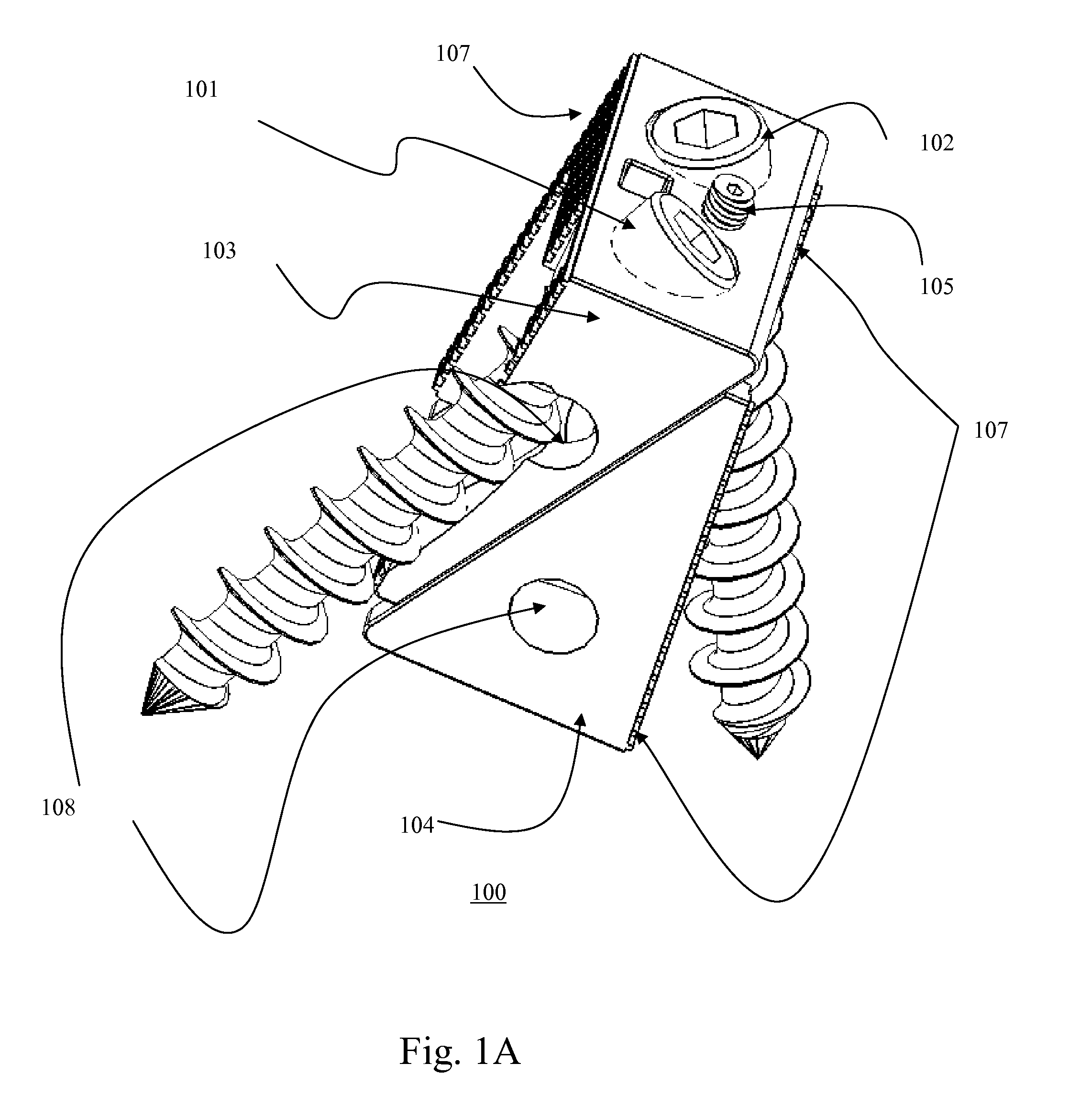
This application is a Continuation-In-Part application of copending application Ser. No. 11/536,815, filed on Sep. 29, 2006, which is a Continuation-In-Part application of copending application Ser. No. 11/208,644, filed on Aug. 23, 2005 for which priority is claimed under 35, U.S.C. § 120; and this application also claims priority under 35 U.S.C. § 119(e) of U.S. provisional application No. 60/670,231, filed on Apr. 12, 2005; the entire contents of all the above identified patent applications are hereby incorporated by reference. The present invention relates to a unique universal bidirectional screw (BDS) system, and in particular its application to the spine, also referred to as bi-directional fixating transvertebral (BDFT) screws which can be used as a stand-alone intervertebral device which combines the dual functions of an intervertebral spacer which can be filled with bone fusion material(s), as well as a transvertebral bone fusion screw apparatus. In the posterior lumbosacral and thoracic spine, BDFT screw/box constructs can be used independently or supplemented with a novel horizontal mini-plate which prevents upward bone graft intrusion into the thecal sac and nerves. In the anterior lumbosacral spine BDFT screw box constructs can be inserted into and supplemented by a circumferential cage. These posteriorly and anteriorly placed stand-alone intervertebral body fusion constructs may obviate the need for supplemental pedicle screw fixation. The present invention also relates to stand-alone or supplemental posterior cervical and lumbar calibrated inter-articular joint stapling devices which may obviate and/or lessen the need for supplemental pedicle screw fixation. The history and evolution of instrumented spinal fusion in the entire human spine has been reviewed in our two prior copending application Ser. No. 14/536,815, filed on Sep. 29, 2006, and Ser. No. 11/208,644, filed on Aug. 23, 2005, the related contents of which are hereby incorporated by reference. Currently the majority of posterior cervical and almost all anterior and posterior lumbosacral and thoracic fusion techniques are typically supplemented with pedicle screw placement. Complications of pedicle screw placement in cervical, thoracic and lumbar spine include duration of procedure, significant tissue dissection and muscle retraction, misplaced screws with neural and/or vascular injury, excessive blood loss, need for transfusions, prolonged recovery, incomplete return to work, and excess rigidity leading to adjacent segmental disease requiring further fusions and re-operations. Recent advances in pedicle screw fixation including minimally invasive and image-guided technology, and the development of flexible rods, imperfectly address some but not all of these issues. Complications of all current spinal interbody fusion devices is their lack of coverage of the majority of the cross-sectional area of the vertebral endplates, and their lack of adequate, if any capacity to penetrate bone, and hence the heightened risk of implant extrusion. Furthermore the bone and biological bone fusion agents which are packed into the intervertebral space can easily blossom and grow upward into the thecal sac causing neural compression, in the absence of a physical barrier between the fusing growing bone, and the thecal sac. Herein we describe multiple device embodiments which combine in a single construct the dual functions of an intervertebral spacer maintaining disc space height, and transvertebral body fusion screws. We also introduce an entirely novel horizontal mini-plate capping off the intervertebral space capable of functioning as a physical barrier preventing upward bone intrusion and/or compression of the ventral thecal sac, and traversing and exciting nerve roots. Furthermore, we present an advanced mechanism in calibrated posterior facet joint stapling compared to our previous designs illustrated in our co-pending patents. We also introduce the entirely novel concept of posterior cervical facet staples to obviate and/or diminish the need for posterior cervical pedicle screw instrumented fusion. Using combinations and permutations of different embodiments of cervical facet staples in a modular manner advances To achieve safe, effective and minimally invasive segmental spinal fusion, applicants propose the use of novel bi-directional fixating transvertebral (BDFT) screws which can be strategically inserted via anterior or posterior surgical spinal approaches into the anterior and middle columns of the interverterbral disc space. In our previous applications these bi-directional screws employed turning a wormed driving screw which turns a spur gear which in turn simultaneously turns a rostral oriented screw into the cephalad vertebral body, and a caudal directed screw into the caudal vertebral body. The vertebral bodies above and below the disc space by virtue of their engagement and penetration by the BDFT screws are thus linked, interlocked, and eventually biologically fused with placement of intervertebral bone agents. In this current application one or more of the described embodiments may eliminate the intervening wormed driving screws and gears required by previous designs, e.g., a gearless screw box is achieved. We have designed a screw box to be placed inter-vertebrally, either unilaterally or bilaterally, in particular, posteriorly between vertebral bodies. The housing screw box incorporates built-in screw and/or drill guides which allow the direct placement and insertion of two self drilling screws which are driven in two opposing directions into superior and inferior vertebral bodies, respectively. One screw within the screw box is angled superiorly, and the other screw in the screw box is angled inferiorly. In yet another embodiment, in addition to these features we designed an expanding screw box with sliding triangular bases to house two screws driven in two opposing directions which can be expanded in two simultaneous directions, height and depth, by turning a built-in screw adjuster. This is accomplished by a combined positioning tool/screw guide/cage expander to further enhance trajectory precision and to simultaneously expand the screw box in height and depth to custom-fit the individual disc space height. This embodiment has two sub-embodiments; one has two laterally oriented BDFT screws, and the other has a lateral and a medial oriented BDFT screw. These innovations represent a continued evolution of our concept of expandable fusion cages described in our previous co-pending patents. In yet another embodiment we designed a screw box which houses only one, instead of two screws. Each box allows the placement of one superior or inferior directed screw on one side (left or right), and the contra lateral screw box device allows placement of an inferior or superior oriented screw which goes in the opposite direction of the contra lateral device. In totality these two separate single screw boxes fuse the superior and inferior vertebrae. The potential advantage of this embodiment is that it diminishes the width of the screw box in cases where it might be favorable to have less nerve root retraction with a smaller width device. In all screw-box embodiments, a rostral-directed screw is passed through one built-in screw guide of the device which then is inserted and screwed into the superior vertebral body. Then a caudaly directed screw is passed through an adjacent built-in screw guide which then is inserted and screwed into the inferior vertebral body. The novelty of this design is the built-in prescribed angles of the integral screw guides which allow the posterior transvertebral penetration into the vertebral bodies. This is a truly amazing feat accomplished in the posterior lumbar spine considering the small anatomically restricted work zone within which to work, which is very narrowly prescribed by obtuse angulations between screw and intervertebral bone surfaces, and by nerve root, facet joint and pedicle. We have also designed a positioning tool for the placement of the non-expandable screw boxes which has a screwdriver with a flexible shaft specifically designed to fit these devices if a straight screw driver impedes screw placement. Hence these external tools provide the means in any circumstance to accomplish precision screw trajectory. The embodiments described herein compared to our previous co-pending patent designs, streamline and ease production of bi-directionally oriented transvertebral screws, and allows placement of longer and wider screws with greater bone penetration to provide yet a sturdier fusion construct. The designs are also easily modifiable for anterior placement into the cervical spine. The expandable embodiment of the screw box can also be enlarged and modified to be suitable for cervical, thoracic and lumber vertebral body replacements. The box casings have multiple perforations to allow both screw traversal and horizontal bone packing preventing upward vertical migration of bone. The boxes prevent subsidence. Both the inside of the denuded intervertebral space, and the screw boxes can be packed with autologous or allograft bone, BMP, DBX or similar osteoconductive material. Posteriorly or anteriorly in the lumbar It is believed that BDFT-screw constructs provide as strong or stronger segmental fusion as pedicle screws without the complications arising from pedicle screw placement which include screw misplacement with potential nerve and/or vascular injury, violation of healthy facets, possible pedicle destruction, blood loss, and overly rigid fusions. By placing screws across the intervertebral space from vertebral body to vertebral body, engaging anterior and middle spinal columns, and not the vertebral bodies via the transpedicular route, the healthy facet joints, if they exist, are preserved. Because this technique accomplishes both anterior and middle column fusion, without rigidly fixating the posterior column, it in essence creates a flexible fusion. This device therefore is a flexible fusion device because the preserved posterior facet joints retain their function achieving at least a modicum of mobility and hence a less rigid (i.e. a flexible) fusion. The very advantage of transpedicular screws which facilitate a strong solid fusion by rigidly engaging all three spinal columns is the same mechanical mechanism whereby complete inflexibility of all columns is incurred thereby leading to increasing rostral and caudal segmental stress which leads to an increased rate of re-operation. Transvertebral fusion also leads to far less muscle retraction, blood loss, and significant reduction in O.R. time. Thus the complication of pedicular screw pull-out and hence high re-operation rate associated with the current embodiment of flexible fusion pedicle screws/rods is obviated. The lumbosacral screw box embodiments and BDFT screws can be introduced via posterior lateral, transforaminal or anterior interbody fusion approaches/techniques. Although one can opt to supplement these screws with transpedicular screws there would be no absolute need for supplemental pedicle screw fixation with these operative techniques. BDFT screw constructs outlined here can also be combined with novel zero-profile horizontal cervical and, lumbar/thoracic mini-plates. Likewise one or two of these devices can be inserted anteriorly with or without circumferential cage supplementation. Because the BDFT screws engage a small percentage of the rostral and caudal vertebral body surface area, multi-level fusions can be performed with these devices. Previous improvements included a novel calibrated lumbar/thoracic facet stapling device which staples the inferior articulating facet of the superior segment to the superior articulating facet of the caudal vertebral segment unilaterally or bilaterally, which may minimize motion until interbody fusion occurs. In the present patent application we introduce a new design of the staple enhancing its calibrating capability. In this patent application we also introduce a novel posterior cervical facet stapling device which staples the inferior articulating facet of the superior cervical segment with the superior articulating facet of the caudal vertebral segment unilaterally or bilaterally. The advantage of cervical facet staples is speed and safety. The risks of cervical facet pedicle screw fixation which include nerve root and vertebral artery injuries are completely obviated. Thus they thereby achieve the same function of pedicle screws without the risks. Placement of different embodiments of the cervical facet staples along unilateral and/or bilateral facet joints in a modular manner, lead to differing degrees of calibrated motion joint motion hence introducing for the first time the concept of calibrated cervical fusion. Currently failed anterior lumbar arthroplasties are salvaged by combined anterior and posterior fusions. BDFT screw constructs could be utilized as a one-step salvage operation for failed/extruded anteriorly placed lumbar artificial discs obviating the above salvage procedure which has far greater orbidity. For example, in one general aspect, a self-drilling bone fusion screw apparatus includes a first sliding box, a second sliding box, positioned relative to the first sliding box, a first screw member having a tapered end and a threaded body disposed within the first sliding box, a second screw member having a tapered end and a threaded body disposed within the second sliding box, and an adjuster for adjusting the height of the sliding boxes. Implementations of this aspect may include one or more of the following features. For example, the first and second screw members may be medially aligned. At least one of the first and second screw members may be laterally aligned. The first and second screw members are laterally aligned. One of the first and second screw members is laterally aligned and the other screw member is laterally aligned. The first and second sliding boxes may be substantially triangularly shaped. The triangularly shaped first and second sliding boxes may include a sliding rail and ridged surfaces. The triangularly shaped first and second sliding boxes may include holes for bone grafts. The adjuster may include a screw. In another general aspect, a self-drilling bone fusion screw apparatus includes a box, a first screw member having a tapered end and a threaded body disposed at least partially within the box and laterally aligned with the box, a second screw member having a tapered end and a threaded body disposed at least partially within the box and laterally aligned with the box, and a plurality of ridges disposed on along the sides of the box. Implementations of this aspect may include one or more of the following features. For example, the apparatus may include bone graft holes. The apparatus may be attachable to a second self-drilling fusion screw apparatus via a plate. In another general aspect, a self-drilling bone fusion screw apparatus may include a first box, a first screw member having a tapered end and a threaded body disposed at least partially within the first box and laterally aligned with the first box, a second box, a second screw member having a tapered end and a threaded body disposed at least partially within the second box and laterally aligned with the second box, and an attachment member for engaging the first and second boxes. Implementations of this aspect may include one or more of the following features. For example, the self-drilling bone fusion screw apparatus may include bone graft holes. The plate may be directly joined to the first and second boxes by a plurality of screws. The attachment member for engaging the first and second boxes may include a plate or the attachment member may include a circumferential cage defining at least one recess. The first and the second boxes may be positioned within or securely held within the recess of the circumferential cage, e.g, with an interference fit. In another general aspect, a tool assembly for manipulating a self-drilling bone fusion screw apparatus includes a handle, a gripper cooperating with the handle and having a plurality of prongs, a screw guide, held in place the plurality of prongs, for controlling the direction of self-drilling screws that are screwed into a vertebral body. Implementations of this aspect may include one or ore of the following features. For example, the tool assembly for manipulating a self-drilling bone fusion screw apparatus may include a key for controlling an adjustment device which controls the height of the self-drilling bone fusion screw apparatus. The tool assembly according to claim may include a driver assembly. The driver assembly may include a handle, a drive bit portion, and a flexible drive shaft extending between the handle and the drive bit portion for manipulating a screw of an expandable or non-expandable screw box. The assembly may include one or more of an expandable screw box and/or a non-expandable screw box. The boxes may include one or more screws. The screw boxes may be joined by or include an attachment member, such as a plate and/or a circumferential cage. In another general aspect, a cervical facet staple includes a curved staple base, at least two prongs attached to the bottom surface of the curved staple base, and an insertion member disposed on the top surface of the curved staple base. Implementations of this aspect may include one or more of the following features. For example, the staple may include at least four prongs attached to the bottom surface of the curved staple base. The insertion member may include a threaded insert. In another general aspect, an impaction tool for a cervical facet staple includes a handle, a stem attached to the handle, a plurality of wings for contacting the cervical facet staple, and an insertion member for coupling the cervical facet staple to the impaction tool. Implementations of this aspect may include one or more of the following features. For example, the handle may include a flattened portion that can be struck by a mallet. In another general aspect, a lumbar facet staple includes a pair of rotating arms, at least two prongs attached to the inner surfaces of the rotating arms, a plurality of spurs attached to one of the rotating arms, and a ratchet attached to one of the rotating arms. The rotating arms and prongs are rotated to a closed position to staple a lumbar facet joint. 1. The Medical Device Referring to The expandable box 100 consists of top and bottom triangular sliding bases 103, 104 ( Transvertebral screw 101 penetrates the top base 103, and transvertebral screw 102 traverses the bottom base 104 of the screw box 100. The two screws 101, 102 traverse the screw box 100 in opposing directions, bi-directionally (whether they are lateral or medially oriented). The external edges of the triangular bases 103, 104 in contact with vertebral body surfaces include ridges 107. This facilitates the screw box's 100 incorporation into and fusion with the superior and inferior vertebral bodies ( The key components of this device include an Allen key 501, a spring 502, a handle 503, a griper 504 and a screw guide 505. The Allen key 501 when inserted in the insertion 514 and turned, turns the screw adjuster ( 2. The Surgical Method Exemplary surgical steps for practicing one or more of the foregoing embodiments will now be described. The posterior lumbar spine implantation of all the screw box 100, 200, 300 embodiments, with BDFT screws, and horizontal mini-plate 400 can be implanted via previously described posterior lumbar interbody fusion (PLIF) or posterior transforaminal lumbar interbody fusion (TLIF) procedures. The procedures can be performed open, microscopic, closed tubular or endoscopic. Fluoroscopic guidance can be used with any of these procedures. After adequate induction of anesthesia, the patient is placed in the prone position. A midline incision is made for a PLIF procedure, and one or two parallel paramedian incisions or a midline incision is made for the TLIF procedure. For the PLIF, a unilateral or bilateral facet sparing hemi-laminotomy is created to introduce screw box 100, 200, 300 embodiments I-III into the disc space, after it is adequately prepared. For the TLIF procedure, after unilateral or bilateral dissection and drilling of the inferior articulating surface and the medial superior articulating facet the far lateral disc space is entered and a circumferential discectomy is performed. The disc space is prepared and the endplates exposed. Then one screw box 100, 200, 300 of either embodiments I-III is placed on either right, left or both sides. Then another screw box of embodiments 100, 200, 300 I-III is placed on the contralateral side. For embodiment I the external screw guide 505/box expander is attached to the screw box ( For embodiments II-III the same method is used for placing screws, except the Allen key 501 is not utilized in the absence of plate expansion. If bilateral constructs have been inserted, bone is packed into the intervertebral space, as well as within the device. Then the horizontal intervertebral zero profile mini-plate 400 is slid beneath the thecal sac and is secured to both left and right screw boxes with small mini-plate screws 210 ( The anterior thoracic and lumbar spine implantation of one, two or three screw box constructs 100, 200, 300 and BDFT screws can be performed in a similar manner to the posterior application. Likewise, a horizontal mini-plate 400 can be used to cap two or three screw box constructs 100, 200, 300 (one placed midline deeply, one placed left and one placed right, forming a triangulation). Alternatively two screw box constructs may be placed into a circumferential ring for anterior placement. Anterior placement of these devices can be performed into the L4/5 and L5/S1 spaces on the supine anesthetized patient via previously described open microscopic or endoscopic techniques. Once the disc space is exposed and discectomy and space preparation are performed, placement of one, two or three screw box embodiments 100, 200, 300 (I-III) or a 2 in I construct can be placed. The screw placement is facilitated by the internal screw guides, and different positioning tools (( The posterior placement of screw box constructs 100, 200, 300 alone or combined with horizontal mini-plates 400 into the thoracic spine can be performed via previously described transpedicular approaches; open or endoscopic. The anterior placement into the thoracic spine can be accomplished via a trans-thoracic approach. Once the disc space is exposed via either approach, any combination of the above mention Embodiments (I-III) can be inserted. Engagement of the devices is identical to what was mentioned above. For posterior placement of cervical facet staple 700, 800 embodiments, after adequate induction of anesthesia the patient is flipped prone and his head and neck secured. A single midline or two para-median incisions are made for unilateral or bilateral or multilevel placement of staples. Ultimately the facet joint is exposed. Alternatively and preferably this can be performed percutaneously under fluoroscopic guidance with intravenous sedation. The staple 700, 800 (Embodiments I or II) is loaded into the impactor 900, 1000. The staple 700, 800 is placed on the two articulating cervical facets, and then impacted into the joint. To achieve modular calibrated fusion different combinations and permutations of cervical facet stales can be inserted ranging from a single unilateral two pronged staple providing a high degree of flexibility to a total of four bilaterally placed four pronged staples 800 (16 prongs) leading to the highest degree of rigidity. Additional bone may or may not be placed in its vicinity to facilitate permanent and solid fusion. This procedure can be performed open, closed, percutaneously, tubulary, endoscopically or microscopically. We have previously described surgical placement of the lumbar facet joint staple in our two co-pending patents. The surgical procedure for this device is identical to that which has been previously mentioned. The present inventions may provide effective and safe techniques that overcome the problems associated with current transpedicular based cervical, thoracic and lumbar fusion technology, and for many degenerative stable and unstable spine disease. These inventions could replace much pedicle screw-based instrumentation in many but not all degenerative spine conditions. The speed and simplicity of placement of cervical and lumbar facet staples, and placement of Lumbar screw box-BDFT constructs far exceeds that of current pedicle screw technology. Furthermore, these devices have markedly significantly decreased risk of misguided screw placement, and hence decreased risk of neural and vascular injury, and blood loss. In the lumbar spine BDFT screw constructs and facet staples could be applied modularly in different combinations to achieve different degrees of rigidity (flexibility). Patients having these devices would have decreased recovery and back to work time. These devices most likely lead to similar if not equal fusion with significantly less morbidity, and hence overall make them a major advance in the evolution of spinal instrumented technology leading to advances in the care of the spinal patient. Another major novelty and advance is the introduction of simple and sale modular calibrated cervical flexible fusion. To our knowledge neither a similar device nor a similar mathematical concept of modular joint flexibility/fusion calibration has been postulated for the cervical spine or for any other articulating joint. To our knowledge there have not been any previously described similar posterior lumbar and thoracic combined spacer and screw constructs. These devices can similarly be modified to stabilize bone fractures throughout the entire body. To our knowledge the description of zero to subzero profile anterior or posterior horizontal spinal plates which traverse the diameter of the disc space has not been previously described. An intervertebral expandable implant with first and second vertebral body engagement surfaces includes first and second implant structures defining first and second angled wedge portions. The first angled wedge portion has first and second inwardly-facing rails and first and second inwardly-facing slots. The second angled wedge portion has first and second outwardly-facing rails and first and second outwardly facing slots. The first implant structure is slidably-engaged with the second implant structure with the first inwardly-facing rail positioned in the first outwardly-facing slot, the second inwardly-facing rail positioned in the second outwardly facing slot, the first outwardly-facing rail positioned in the first inwardly-facing slot, and the second outwardly-facing rail positioned in the second inwardly-facing slot. 1-10. (canceled) 11. An intervertebral expandable implant having an inferior surface for engaging an inferior vertebral body and a superior surface for engaging a superior vertebral body, wherein the superior surface is positioned opposite of the inferior surface, the intervertebral expandable implant comprising:
a first implant structure defining the inferior surface and a first angled wedge portion that is angled with respect to the inferior surface, wherein the first angled wedge portion comprises a first inwardly-facing rail and a second inwardly-facing rail, wherein a first inwardly-facing slot is defined at a location adjacent the first inwardly-facing rail between the first inwardly-facing rail and the inferior surface, wherein a second inwardly-facing slot is defined at a location adjacent the second inwardly-facing rail between the second inwardly-facing rail and the inferior surface, wherein the first implant structure defines first and second opposing side surfaces positioned on opposite sides of the inferior surface, wherein the first implant structure defines at least first, second, and third openings with the first opening extending through the inferior surface of the first implant and the second and third openings extending through the first and second side surfaces; and a second implant structure defining a second angled wedge portion that comprises a first outwardly-facing rail and a second outwardly-facing rail that faces outwardly in a direction opposite that of the first outwardly-facing rail, wherein a first outwardly-facing slot is defined at a location adjacent the first outwardly-facing rail, wherein a second outwardly-facing slot is defined at a location adjacent the second outwardly-facing rail, wherein the first implant structure is slidably-engaged with the second implant structure such that the first angled wedge portion engages the second angled wedge portion with the first inwardly-facing rail of the first implant structure positioned in the first outwardly-facing slot of the second implant structure, the second inwardly-facing rail of the first implant structure positioned in the second outwardly facing slot of the second implant structure, the first outwardly-facing rail of the second implant structure positioned in the first inwardly-facing slot of the first implant structure, and the second outwardly-facing rail of the second implant structure positioned in the second inwardly-facing slot of the first implant structure. 12. The intervertebral expandable implant of 13. The intervertebral expandable implant of 14. The intervertebral expandable implant of 15. The intervertebral expandable implant of 16. The intervertebral expandable implant of 17. The intervertebral expandable implant of 18. The intervertebral expandable implant of 19. The intervertebral expandable implant of 20. The intervertebral expandable implant of 21. The intervertebral expandable implant of 22. An intervertebral expandable implant having a first vertebral body engagement surface and a second vertebral body engagement surface positioned opposite of the first vertebral body engagement surface for engaging inferior and superior vertebral bodies, the intervertebral expandable implant comprising:
a first implant structure defining the first vertebral body engagement surface and a first angled wedge portion that is angled with respect to the first vertebral body engagement surface, wherein the first angled wedge portion comprises a first inwardly-facing rail and a second inwardly-facing rail, wherein a first inwardly-facing slot is defined at a location adjacent the first inwardly-facing rail between the first inwardly-facing rail and the first vertebral body engagement surface, wherein a second inwardly-facing slot is defined at a location adjacent the second inwardly-facing rail between the second inwardly-facing rail and the first vertebral body engagement surface, wherein the first implant structure defines first and second opposing side surfaces positioned on opposite sides of the first vertebral body engagement surface; a second implant structure defining a second angled wedge portion that comprises a first outwardly-facing rail and a second outwardly-facing rail that faces outwardly in a direction opposite that of the first outwardly-facing rail, wherein a first outwardly-facing slot is defined at a location adjacent the first outwardly-facing rail, wherein a second outwardly-facing slot is defined at a location adjacent the second outwardly-facing rail, wherein the first implant structure is slidably-engaged with the second implant structure such that the first angled wedge portion engages the second angled wedge portion with the first inwardly-facing rail of the first implant structure positioned in the first outwardly-facing slot of the second implant structure, the second inwardly-facing rail of the first implant structure positioned in the second outwardly facing slot of the second implant structure, the first outwardly-facing rail of the second implant structure positioned in the first inwardly-facing slot of the first implant structure, and the second outwardly-facing rail of the second implant structure positioned in the second inwardly-facing slot of the first implant structure; and an adjusting screw having a threaded shaft, wherein the second implant structure defines a screw hole, wherein the threaded shaft of the adjusting screw is positioned in the screw hole of the second implant structure, wherein the first implant structure defines a space that is larger than a diameter of the threaded shaft of the adjusting screw so as to allow the first implant structure to move with respect to the adjusting screw along a direction normal to the first vertebral body engagement surface when the intervertebral expandable implant is expanded, and wherein rotation of the adjusting screw with respect to the second implant structure moves the second implant structure with respect to the first implant structure to slide the first angled wedge portion with respect to the second angled wedge portion and expand the intervertebral expandable implant. 23. The intervertebral expandable implant of 24. The intervertebral expandable implant of 25. The intervertebral expandable implant of 26. The intervertebral expandable implant of 27. The intervertebral expandable implant of 28. An intervertebral expandable implant having a first vertebral body engagement surface and a second vertebral body engagement surface positioned opposite of the first vertebral body engagement surface for engaging inferior and superior vertebral bodies, the intervertebral expandable implant comprising:
a first implant structure defining the first vertebral body engagement surface and a first angled wedge portion that is angled with respect to the first vertebral body engagement surface, wherein the first angled wedge portion comprises a first inwardly-facing rail and a second inwardly-facing rail, wherein a first inwardly-facing slot is defined at a location adjacent the first inwardly-facing rail between the first inwardly-facing rail and the first vertebral body engagement surface, wherein a second inwardly-facing slot is defined at a location adjacent the second inwardly-facing rail between the second inwardly-facing rail and the first vertebral body engagement surface, wherein the first implant structure defines first and second opposing side surfaces positioned on opposite sides of the first vertebral body engagement surface; and a second implant structure defining a second angled wedge portion that comprises a first outwardly-facing rail and a second outwardly-facing rail that faces outwardly in a direction opposite that of the first outwardly-facing rail, wherein a first outwardly-facing slot is defined at a location adjacent the first outwardly-facing rail, wherein a second outwardly-facing slot is defined at a location adjacent the second outwardly-facing rail, wherein the first implant structure is slidably-engaged with the second implant structure such that the first angled wedge portion engages the second angled wedge portion with the first inwardly-facing rail of the first implant structure positioned in the first outwardly-facing slot of the second implant structure, the second inwardly-facing rail of the first implant structure positioned in the second outwardly facing slot of the second implant structure, the first outwardly-facing rail of the second implant structure positioned in the first inwardly-facing slot of the first implant structure, and the second outwardly-facing rail of the second implant structure positioned in the second inwardly-facing slot of the first implant structure, wherein the intervertebral expandable implant defines first and second screw guides positioned and configured to guide screws into the superior and inferior vertebral bodies, and wherein at least one of the first and second implant structures defines at least one of the first and second screw guides. 29. The intervertebral expandable implant of 30. The intervertebral expandable implant of an adjusting screw having a threaded shaft, wherein the second implant structure defines a screw hole, wherein the threaded shaft of the adjusting screw is positioned in the screw hole of the second implant structure, wherein the first implant structure defines a space that is larger than a diameter of the threaded shaft of the adjusting screw so as to allow the first implant structure to move with respect to the adjusting screw along a direction normal to the first vertebral body engagement surface when the intervertebral expandable implant is expanded, and wherein rotation of the adjusting screw with respect to the second implant structure moves the second implant structure with respect to the first implant structure to slide the first angled wedge portion with respect to the second angled wedge portion and expand the intervertebral expandable implant. 31. The intervertebral expandable implant of 32. The intervertebral expandable implant of 33. The intervertebral expandable implant of 34. The intervertebral expandable implant of 35. The intervertebral expandable implant of 36. The intervertebral expandable implant of FIELD OF INVENTION
Description of the Relevant Art
SUMMARY
BRIEF DESCRIPTION OF DRAWINGS
DETAILED DESCRIPTION OF THE INVENTION