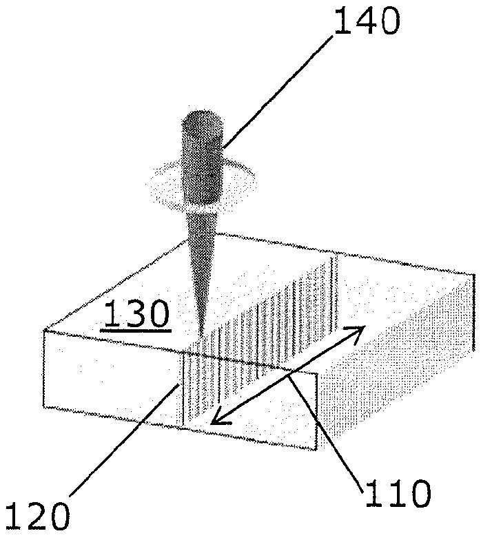
사파이어 기판을 레이저로써 레이저 절단하는 방법 및 일련의 결함을 갖는 엣지가 형성된 사파이어를 포함한 물품
The present application a American man runaway application to the 17 December 2013 circle number number 61/917,082 call and, 10 July 2014 circle number application to a American man runaway number 62/022,890 call and, 31 October 2014 and priority claims application to call a American patent application number number 14/529,976 inputted from the user, these patent document contents of a reference a is integrated to both the specification. The present application the sapphire substrate laser as a laser cutting method and a set of deficiency is removed having a sapphire including relates to article. Material to the field of laser processing of cutting, drilling, milling, welding, including such as melt wide variety of different types of examples of the applications is material is. In these applied, special interest from the sapphire one in particular, it relates to any shape such as, separating the sections, different types of of the substrate material cuts or separation portion is. Sapphire excellent in strength, hardness, scratch properties and large, and in addition 150 nm to 5500 nm. highly wavelength of light. Sapphire electrical characteristics, mechanical properties, thermal properties and excellent the same optical properties in a rate determined by the overlapping combinations special light source in which various kinds is carried out by using an acidulous applications. These application of this method, sufficient science device, and durable window, bar code scanner, watch crystal and movement bearing (movement bearing), and the purpose of special solid-state electronic product (an integrated is a circuit by these most) insulating for use as a substrate a very thin electronic wafer optical infrared such as.. In addition GaN (gallium nitride) based on a sapphire (growth) of power generated by the device, such as a substrate, non-conductive for used in the semiconductor industry. In particular, a sapphire low but electrically conductive, however greater relatively from thermally conductive. Therefore, excellent sapphire provides electrical isolation while distributing materials that are, used for generating an integrated all operating simultaneously many provided for conducting heat which helps. More recent to, home appliances (consumer electronics products) in multi smart phone, screen cover and touch application is provided as an alternative material of wet liquid to flow down. Since the extremely hard material-is sapphire, the substrate material is for producing part from a conductive primary. process the cutting conductive one. Typically, the cutting of the pattern on a substrate and [...] to diamond-tip edge first using can be achieved. Therefrom, completely portion profile [...] tracked to effect detachment of the also provided a method of fabricating and a substrate along profile propagates through the influence of a mechanical force that receives or, or substrates into a plurality of unit cell [...] a circular diamond blade followed by by path number 2. Diamond edges and the width of the first small but finite processing diamond edge is to precharge the width of the separate the portions between two 2 "street (street)" (typically greater than about 40 micro m). to leave. Substrate of the parts removed from edge and to maintain the quality of fault large substrate (catastrophic) and in addition said speed command value is not in order to avoid cracking, diamond tip, which here extend the processing edges, low rate should necessarily operated. Furthermore, since the wear, edge wear of diamond tip in one weighting register per the wafer by edge necessarily need to be replaced which often, the manufacturing process and slow down the. an increase in a cost. Eventually, cause mechanical scribe processing of cracking, this can be damaging the substrate decreases the yield (typically yield about 70% randomly choosing). Sapphire cutting and the other associated with the processing of the parts removed the conductive relative to shape. Due to line properties of the outside crystal sapphire, fission and separation one of a plane preferentially crystal plane alignment with a straight line generated from. However, this same hardware more feature a complex shaped sapphire portion. difficulties and separation for cutting. For example, circular derived alignment and a crystal puller for the shape according to stress, square, of separating from a substrate when circular shape, crack propagation an intended circular path structural and instead process recursive virtual machine instructions can be disposed near one crystal plane path of least resistance along a plane can be occur along. Processing development and cost from a specific point of view, cutting and surface of the sapphire substrate at many to improve the separation. opportunity. Faster and to separation failure of sapphire, and cleaner, are produced at a lower cost than, and repeatable than reliable than greater interested in method (current embodiment than that which would be in the market today). In various alternative techniques, laser separation different approach is attempted with which experiment carried out at a. Technique: 1) required portion (or partially) between boundary part of matrix surrounding substrate and removing actual material; 2) is followed step stage difference plate 2 the required feature profile according to cracking visitor periphery of a material elastically grown at low temperature and the generation of deficiency in most of the material; and 3) thermal stress propagation of crack by separation; as. various. These laser cutting processing competitive techniques (mechanical [...] rupture, the pressure water jet and ultrasonic milling, such as) accuracy compared to, and finishing edge excellent low residual stress and a connection structure is a structural position of the input wheel techniques and economical. Nevertheless several arbitrarily shaped sapphire for cutting and removal for processing is a need for an improved continuously. The present specification to a disclosure embodiment relate several arbitrarily shaped from sapphire and other substrate material for cutting and for separating the relates to laser processing. Developed laser method the profile of the desired thermal stress and from a substrate based on complete or manual separation of portion for laser separation (tailor) can be adjusted. The present method the spaced-apart relationship from the substrate required to be a and conform to the shape least the exposed portion of the conductive, VHF-for making line (fault) flaw of signals by modulation and demodulation comprises the use of pulse laser. Flaw line false to a different direction while avoiding and damage crack propagation, form parts having the a to a location which facilitates decoupling of preferential crack propagation to form a path of. VHF that the laser pulse substrate and part completely automated, to remove a different heat that affect separation or won for generating stress CO2 laser extent, optionally warmed by means of. is capable. In one embodiment, discrete portions of material for forming laser cutting of the pulse laser beam method laser beam focus line focus 54 step, material in the material in said laser beam focus lines for making holes or line deficiency the induced absorption the line focus beam using a laser source to generate provide a way to make the connected further, laser as deficiency plurality of material to form a line, with each other and relation to translation the materials or laser beam, and a plurality of holes or deficiency easily apply the laser beam IR on line includes. Laser beam focus line along the direction of beam propagation and which may be right. Can be the sapphire material. Pulsed laser beam pulse duration is about 1 greater than picocell picocell or may be less than about 100, or about 5 greater than about 20 picocell picocell can be less than seconds. The repetition rate pulsed laser beam of 1 kHz to 2 MHz, or is 650 kHz to 10 kHz. Pulsed laser beam of material greater than 40 μ J per mm thickness, measured in the case of solid material material may have a average laser power. Pulse at least 2 one burst of pulses can be made in. Within a burst of 1 nsec to 50 nsec pulse, or 10 nsec to 30 nsec, or 25 nsec to 15 nsec can be and separated by a duration of. Multiple burst can be applied to a material, wherein each a burst 2 and includes a pulse one or more burst repetition frequency. belonging to about 1 kHz to about 2000 kHz. Pulsed laser beam is, material is substantially at a wavelength such that the amorphous carbon is transparent, the selected wavelength can take the. Laser beam focus line about 0.1 mm to about 100 mm, or about 0.1 mm to about 10 mm may have a length in the. Laser beam focus line about 0.1 micro m to about 5 micro m can take the spont diameter average. The present method to separate part from a material, until edge the wafer while holding the wafer in part from edge near-end material, or material until edge the wafer while holding the wafer in part from such that the distal edge further a step in which the IR laser may further include any. Said IR in addition easily apply the laser beam the step CO2 laser beam, whereby the support is brought further may include. IR laser beam spot size of about 2 mm to about 20 mm can be (defocus) defocused to. IR laser beam of material near the distal edge of material from a can be easily apply the edge relation to. Deficiency series of article and manufacturing method thereof and comprises edges, wherein each deficiency line extends at least 250 micro m, said deficiency line and has a diameter of less than m micro 5, said edge a surface roughness Ra has a < 0.5 micro m, material, and glass edge a portion under the surface of m is < 100 micro damage (subsurface). In addition micro < 75 damage a portion under the surface of edge glass can be m. Deficiency line are woven into total thickness of the article may be proposed. The distance between line deficiency greater than 0.5 micro m can be about 15 micro m hereinafter, a thickness of the article and. can be smaller than the 1.5 mm. A sapphire may comprise an article. Article in addition circular disk or may be is fixed while layer is sapphire or may include a. Glass the thickness of the substrate 100 microns to 1 mm and the shaft transfers the, sapphire and a the thickness of a layer can be 1 microns to 600 microns. In another embodiment, laser cutting of material the method : (i) laser beam focus line step 54 focus pulse laser beam; said laser beam in the material in material (ii) focus line deficiency line, in the induced absorption said line focus beam using a laser source to generate provide a way to make the connected further material; said deficiency plurality of (iii) including line, said flaw in the material (ii) and said (i) lines repeatedly executing a maintaining; IR on line flaw (iv) said and provide a way to make the connected further laser beam; includes. Flaw line linearly or, curved or can be or circular. Further IR laser beam, along a line the flaw provide a way to make the connected can be fracture a material. These embodiment relate reduced laser power, reduced surface below deficiency, improved processing clean, complex profile generation of different sizes and shape of, and process step removal of complete cut portions as including separation has many benefits. The present invention refers to laser cutting of material relates to method, Laser cutting of the method said material: Pulse laser beam step 54 focus line focus laser beam; Said deficiency, along a line focus laser beam in the material the induced line, in said absorption generated in material said laser beam focus line provide a way to make the connected further material; Said plurality of material said laser as to form line deficiency, relation to with each other and said laser beam that translates the or materials; and Plurality of deficiency on line provide a way to make the connected further laser beam IR; includes. The present invention refers to relates to article, A sapphire consists said article, said deficiency series of article and manufacturing method thereof which comprises edges, in this case each deficiency line extends at least 250 micro m, said deficiency is smaller than the diameter of the line m micro 5, said edge a surface roughness Ra has a < 0.5 micro m, and damage a portion under the surface of said edge is < 100 micro m. The present invention refers to laser cutting of material relates to method, Laser cutting of the method said material: (I) laser beam focus line step 54 focus pulse laser beam; (Ii) said deficiency, along a line focus laser beam in the material the induced line, in said absorption generated in material said laser beam focus line provide a way to make the connected further material; Said deficiency plurality of (iii) including line, said flaw in the material (ii) and said (i) lines repeatedly executing a maintaining; and IR laser beam (iv) said flaw line on provide a way to make the connected further; includes. Drawing with an said lubricious is described in the exemplary embodiment is described that more specifically to the first deoxygenator followed, in said drawing the same component number the same member been used so as to direct. According to drawing is belonged to thereby, the cold air flows only is un-gear described embodiment is intended to. Also following the next as 1c-degree 1a: also the 1a a laser line, in flaw through a sample indicative of the drawing and; after the separated 1b also a deficiency and drawing edge; also 1c is of the separated edges. 2a and 2b also positioning of the laser beam focus line, i.e., an absorbent derived, along a line focus due to a material transparent to laser wavelength for treating is indicative of the drawing. Also 3a for the laser drilling is drawing of optical assembly. Also the 3b-4-degree 3b-1 said substrate the laser beam focus line said differently position by a variety of processing a substrate is indicative of a likelihood a drawing. Figure 4 shows a laser drilling also for. the surface of a optical assembly number 2. Also 5a and 5b for the laser drilling is drawing of optical assembly number 3. For laser drilling also Figure 6 shows a multiplex optical assembly number 4 is that the. Also 7a-degree 7c the material for the laser processing of different characteristics for indicating a (regime) is drawing. The focus it fixes, support 7a also shown a laser beam not; 7b also the spherical lens by a centralized shown a laser beam; also the 7c by a contact lens Fresnel or diffraction evil at the time of cone concentrated. mm for matching laser beam. Also laser seconds picocell has 8a as a function of time for. indicates the laser radiation. Each include pulses one or more sub-radiation pulses capable and is characterized by "burst". A time corresponding to the pulse duration, pulse separation of between, and is indicated separation between bursts of constitution :. The 8b also cutting straight surface of the sapphire substrate at thickness of 0.55 mm for representing an Image 66 is photo. Figure 9 0.55 mm thickness and like samples of separated sapphire is electrophotographic indicating a button. Various button in order to manually been isolated, a portion CO2 using a laser partially been isolated another portion CO2 laser as completely been isolated. 10a and 10b also made as laser seconds picocell has won and release line (also 10a) and, first plates and for a next source to emit for example a light button CO2 including laser tracking (also 10b), flaw line drawing sequence is perforated. An exemplary embodiment disclosed is below substracte. A disclosure embodiment relate any-like substrate made of a sapphire includes precision cutting and removal for. providing for the handling laser. Sapphire-containing substrate of a purely sapphire or, one or more other material with or the synthetic sapphire, sapphire blend (blend) or, sapphire-coated, or multi-, having merged sapphire material. In one embodiment, sapphire-containing is attached to and layer is a sapphire substrate, joined or, laminate or, is glass or coating. Sapphire to outweighs wealth, the present specification generally the a sapphire substrate is sapphire-containing substrate extend through the. is considered to be. Processing debris negligible interference, preserve the strength and partial deficiency minimum for low surface for edge damage below a controllable manner having and isolated portion. The selected method laser cutting a material transparent to laser wavelength very suitable.. Preferably contains from selected laser wavelength can be is substantially transparent (i.e., material depth of m approximately 10% purpose of less, more preferably about 1% absorbent be smaller than present). The present method of 0.55 mm on both sides description thickness of sheet abraded C-axis cutting made of a sapphire is performed by using a close-of wet liquid to flow down. Basic the treatment step creates of the parts removed form depicting the flaw line so as to produce by a rope. using laser pulse VHF. Flaw line and crack propagation according to prestretch and for separating and feature from matrix substrate of a minimal resistive path. The originally laser separation method manual separation of shape sapphire substrate, partial isolation or fully configured to separable can be and adjusted. According to method laser substrate below, means of a single light-pass as, laser below the surface upon which damage without generating extremely and debris (< 75 micro m, often < 50 micro m), a significantly through or materials to a substrate fully controlled is utilized to generate a plastic body, plastic lid on-line can be. The skin treating makes numerous content completely in-the-glass thickness pass is often necessary which pierce a, removing material (ablate) laser and the typical bandwiths and spot-feature and using the opposite is, a large amount of debris is ablation processing is formed from, a wider surface and below (> 100 micro m) and edge chipping damage (chipping) which has a weight corresponding to weight. As used in the present specification, according to the present invention under the surface damage laser the substrate being processed or material in peripheral surface of the parts removed from maximum size of structural unsecure part (for example, length, width, diameter). mixture by the addition of an initiator. Structural is unsecure since the extend from the surrounding surface, in addition the present invention according to damage under the surface damages arise from processing laser maximum depth from peripheral surface may be-excited. The peripheral surface of the parts removed of the parts removed edge or edge surfaces the present specification can be referred to in. Structural unsecure part cracks or void (void) and the shaft transfers the, substrate or of the parts removed from the material to break up or crushing the triggerable the can be represent a point on a mechanical weakness. Under the surface damage by minimizing the size, the present method of the parts removed the combined and structural mechanical strength to-shaping. Damage depth of approximately 100 micro m hereinafter under the surface, or depth of 75 micro m hereinafter, or depth of 60 micro m hereinafter, or 50 micro m hereinafter of depths can be defined, and the cutting of the only low debris to generate the objective compound.. Therefore, one or more high energy pulse and energy pulse bursts of using one or more to obtain a desired transparent material (i.e., diameter of < 0.5 마이크로 m 및 >100 nm) elongated deficiency line (in addition, punching or damage track by referred to in the present specification) can be for making. The apertures are of laser modified by exhibits area of the substrate material. By laser induced modifation of the substrate material structure position of weak section mechanical degradation of. a. Structural collapse, and a press-bonding, melt, (dislodging) of material, rearrangement, and includes a narrow distribution. The apertures are of and extend within the interior of the substrate material calculates cross-sectional shapes of the laser (a generally circular) consistent with has cross-sectional shape. The mean average diameter of the perforated micro 0.1 m to 50 micro m, or 1 m to 20 micro micro m, or m to 10 micro m micro 2, or 0.1 micro m to 5 micro m can be. In various embodiment, the apertures are of "through hole" and, of the substrate material from the upper extending in use bottom is open channel perforated. In various embodiment, the apertures are of continuous open channel not be by the laser can be a solid material to b disengaged from the substrate material may include a section of. Materials separation drilling a space defined by the. partially blocking a or disconnecting an input. One or more open channel (is not blocked dimensions) between section the of the material on which. may be dispersed with low. The diameter of the open channel or < 1000 nm, or < 500 nm, or < 400 nm, or < 300 nm, or 750 nm to 10 nm, or 100 nm to 500 nm can be. The present specification to through holes are arranged in a disclosure in the embodiment receives or or modified region prevent troubles from occurring, or a material (for example, pressed or, molten or, or otherwise modified) the, preferably < 50 micro m (for example, < 10 micro m) vehicle has a diameter of. For example the apertures are of individual, hundreds kilohertz made possible by the fact that the made at speeds in the order of (for example, perforated six Figures per second). Therefore, by relative movement between material source for emitting laser, these the apertures are of can be arranged adjacent to each other (as needed sub-microns to limited rpm varying space). Separation, the space (pitch) the tape are selected to. Number 1 in step, or sapphire substrate, or sapphire layer is in place and is removable glass ther the thickness of the wafer for a the glass substrate and said through a thickness of the sapphire layer passes therethrough by a large aspect ratio that concentrated in focus line (condensed) is irradiation by pulsed laser beam VHF. The glass substrate is connected on said glass, indium gallium nitride, sapphire when having an ECC layer and a method, said thickness glass substrate 100 micro m to 1 mm and the shaft transfers the, layer of, for example, sapphire thickness range 600 micro m thick from a thin coating which until layer, and a sapphire greater than 600 micro m excessive the thickness of a layer can be expected to be to broken. VHF pulse laser beam made therewith such in the volume of high energy density, is modified through the effect nonlinear material. Laser beam linear effects, to transfer energy from the provides a mechanism for, vertical deficiency can be line. Triggerable (trigger) for this high optical strength non-linear absorption without being aware of a generates no. it is important. Strength threshold value below for non-linear effects, , its first and transparent heat or laser material remains of the state. Required line or path a laser by scanning, narrow flaw line (plurality of vertical deficiency limited rpm formed line width) separated from the substrate to form a or peripheral portion shape that the portion is to be is made in. High strength laser beam induced by in an linear effects, includes MPa (multi-photon absorption). MPa has a smaller energy state (typically ground state) more energy from material with excite state (excited state), at the same or different frequency plurality of (one or more 2) is simultaneous absorption, a photon. Excited state excited electronic States or ions can be status. Material, a larger proportion of the energy state and 2 difference of energy between a small amount of energy state, a photon energy is equal to the sum of one or more.. The non-linear processing and MPa, the i.e. generally linear absorbing than is that weaker degree some win of meter. The MPa, strength of said MPa, a larger proportion of the light intensity or square is determined according to which differ from each other in and linear absorbing in that, effecting non linear optical is boride treatment. In normal light intensity, the MPa. negligible interference. Extremely if light intensity (energy density), laser source (in particular, pulse laser source) such as zone focus of, , it-of-interest has MPa optical source is a large area has been sufficiently the energy density of measurable in material in effect in the. Focus within the region of, result in a low ion energy density can be and sufficiently large to allow. In level won, individual atoms of the ionization has a separate energy requirements. The commonly used glass various element (for example, Si, Na, K) relatively few has ionizing energy (- 5 eV). Contains of MPa, about 248 nm wavelength is in a range from -5 eV to produce ionization in linear may be required. As MPa, between the state disconnected energy by -5 eV ionisation or the excitation 248 nm to longer wavelengths than. can be accomplished, for. For example, photons having a wavelength of 532 nm -2.33 eV of energy and, having two 2 532 nm wavelength the component is no longer required, the photons having for example, two-photon absorbance (TPA) in 2-4.66 eV transitions between the state disconnected energy by is able to derive a (transition). Therefore, atom and coupled (bond) or exciting the selected from zone of material can be ionized, said zone of a laser beam in an energy density for example, excitation energy required half of a laser having non-linear wavelength greater sufficiently to derive TPA. MPa the adjacent atom or an coupled local of binding atom or an excited from can result reconstitution and separation. Bond or in the configuration final modifation MPa is of a material generating thermal non-disclosed are methods of removing and material from of zones can result [...]. Removal of this material allows for a mechanical or thermal stress when acted upon by a, stresses that would weaken mechanically material crack or crushed more insensitive to structural deficiency (for example, deficiency line, damage line, i.e. "perforated"). By controlling the disposed boring, by applying spherically path or occurrence of cracks can be finely featured precision micro-machining of material can be achieved. Series of perforations formed by non-volatile memory elements is considered line flaw by applying spherically can be in and materials corresponding a structural weak section in the region of. In one embodiment, the beam output by the laser micromachined parts from the treated material which comprise separations of, in this case said derived by a laser portion MPa effect through the boring closed profile or a wiring determined by finely featured vibration. The present specification as used in the, closed profile is formed by laser line term mixture by the addition of an initiator path of the apertures, wherein said path is a to itself at locations. The inner contour of the-forming edges, the final shape which case path of material and encapsulated completely by a portion exterior to. The one end line the flaw having vertical deficiency if made, separation: 1) flaw line or in passive or mechanical stress at the surroundings of said flaw line; stress or pressure together by to fracture the junction the area and the area is still to effect detachment of the flaw line opposing sides of a can be made the resultant structure so that the tension pulls; 2) entire self-separation some or separation is to derive vertical deficiency flaw to receive tension line stepping compartment stress the gate line and a heat source that use; can generate a through. In both instances in said, separation laser scan speed, laser power, lens parameter of, pulse width, repetition rate such as processing parameters is determined according to. The present application for to the edge of the parts removed the minimally as debris and negligible interference, a controllable manner several arbitrarily shaped sapphire or of another substrate precision cutting and removal for provides laser method and apparatus. Of the parts removed edge damage to the prior art said and cutting processing following common characteristics of the parts removed weak section in the. The present method preserve the strength of the parts removed the edge to. order to avoid damage. Developed laser method (low laser intensity) linear characteristic of the power laser (regime) according to transparency of the substrate material to wavelength ratios within.. Transparency feature laser beam formed by damage under the surface from zone and a substrate as well as for reducing the damage on the face of an inhibit or. Another feature of the this processing made by pulse laser VHF deficiency line (in addition punching or damage track by referred to in the present specification) is of large aspect ratios. Of the substrate material from the top surface deficiency line extending bottom surface can be produced. Deficiency or pulsed pulses or one line by during a single burst can be made if necessary, additional pulses or or a burst affected areas (for example, depth and width) extended portion of can be used to augment. Also 1a-degree 1c as shown in, the VHF method a cutting and isolation of sapphire pulse laser (140) substrate material (130) plurality of vertical deficiency line (120) is formed curving phenomena of a line (110) creating the based having incrementally-differing dimensions. Material (130) for processing for a selected laser parameters and material properties (absorbent, CTE, stress, composition, such as) according to, flaw line (110) alone only creating a self-separation can be sufficient to derive a. In this case is, tension/bending power, heating, or CO2 2 such as a laser do not go first separation process is required. Used to determine the air volume in various, made simultaneously-coupled with a line curving phenomena of a sufficient separation without the need for difference can be 2. These steps is required if, for example laser number 2, portion a heat stress of. and may be used to create. Sapphire used to determine the air volume in, separation, flaw line after have been generated, by applying mechanical force to the, or substrate portion from a heat source for making and the thermal stress (for example, infrared laser, for example CO2 laser) by using, can be achieved. Other digital signal to an CO2 laser only disclosure separation after which the finishing separation manually by a rope.. Selective CO2 laser separation for example, 10.6 micro m a defocused emanating from cw laser diode having leaky waveguide structure duty cycle (duty cycle) of as power manipulated by controlling, is achieved. A redirecting (i.e., feature spot size includes the defocused spot size said degree) is than the first spot size to change an thermal stresses is derived by is carried out by using an acidulous. Defocused laser beam a laser wavelength diffraction minimum size that approximates the spot-restricted spot size larger than the size includes these laser beams for making. For example, about 7 mm, 2 mm and 20 mm of defocused spot size is for example, CO2 can be used relative to the laser, this diffractive-limiting micro 10.6 m a given spot size is, significantly smaller than of emission wavelength. Flaw line (110) according to direction of adjacent deficiency line (120) the distance between for example, 0.25 micro m to 50 micro m, or 0.50 micro m to about 20 micro m, or 0.50 micro m to about 15 m micro, or 0.50 micro m to 10 micro m, or 0.50 m to 3.0 m micro micro, or 3.0 micro m to 10 micro m can be. Various for making line deficiency method is present. The method an optical forms a focus line toward laser beam and spherical lens, evil at the time of cone (axicon) lens, diffraction element, or and a linear area using other dots forming the method, can take a multitude of forms. Laser (pico seconds, imprint, such as) and wavelength (IR, green, UV, such as) of type in addition, sufficient optical strength nonlinear optical effect through the substrate material (for example, sapphire or sapphire which is disposed a glass) (breakdown) or that in the event of the failure of a zone is reached, may be varied. Sapphire layer for example, glass substrate can be joined to the top of the magnet. Glass substrate has a for example, of Corning Eagle X6® high-performance such as glass, or soda-lime such as glass includes release low cost. The present application in, VHF pulse laser is constant and, controllable and repeatable manner vertical large aspect ratios is used to fashion a line deficiency. A data storage medium such deficiency line enabling the generation of an optical setup can inhibit the growth of hematopoietic stem 15 January 2013 and below lubricious patent application number number 61/752,489 American a application to and described in, a reference a contents of said patent document specification is integrated both. VHF essence of such general outline (duration imprint or picocell) Bessel of a beam of large aspect ratios, taper with low compression load the microchannels have an zone so as to produce optical lens assembly by a rope. element is not used and thus light lens evil at the time of cone. Makeup alternatively, in large aspect ratios evil at the time of cone substrate material (the long dimension and small diameters), and cylindrical shape for rotary type pulp zone. switching unit to effect a centralized laser beam. Concentrated laser beam generated by of high strength due to, substrate material and method for controlling angle between laser electromagnetic fields further comprises a non-linear action occurs and laser energy substrate is transmitted to the solenoid housing and flaw line component of the. formation of a deficiency. However, a layer of material which does not having a great strength of the laser energy area of (for example, substrate surface, central convergence line surrounding volume of the substrate) in, said transparent and relative to the laser material said material to transfer energy at said laser from a mechanism for being aware of a it is important that no.. As a result, laser intensity transitions into non-linear threshold value when below, signal being nothing substrate. Also surfaces of a 2a and 2b again, material for laser drilling when seen along the direction of beam propagation and which method, laser beam focus line (2b) to pulsed laser beam (2) includes 54 relating to the object. Laser beam focus line (2b) in a different manner, for example, Bessel beam, Airy beam, Weber beam and Mathieu beam (i.e., non-a diffracting beam) which may be made, the intestinal beams (field) Gaussian profile action than transversal direction (i.e., propagation directions) (decay) reduced more slow have a special aberration can be written as typical of those by. As shown in 3a also, laser (3) (not shown) the laser beam (2) emitting, the laser beam defining an optical assembly (6) incident upon, portion (2a) has. Optical assembly (6) the beam direction according to (length of line focus (l)) formed extended range on line focus a laser beam in an output side (2b) (turn). wheel incident laser beam. Planar substrate (1) a laser beam (2) of laser beams focus line (2b) to at least partially overlap. positioned in the path beam. Member number 1a the laser or optical assembly (6) each surface of the planar substrate facing and SNR is not within the predetermined range, the substrate 1b number member and (1) opposite surface also indicate and. Substrate or material thickness (plane (1a and 1b) to, i.e., substrate perpendicular to a plane in measured the present embodiment) along which a member number represented by d.. Also as indicated by the 2a, substrate (1) (or sapphire base material laminated glass) by substantially perpendicular to the axis along which the longitudinal beam and optical assembly according to (6) made by the same focal line (2b) is 32 (steps tray reversing unit vertically of the drawings said substrate). If viewed along beam direction, substrate, focus line (2b) surface of the substrate (1a) surface of the substrate starts before the (1b) manner to a cage by stopping power prior to, i.e. focus line (2b) and terminates in said substrate still the surface (1b) does not extend beyond the in such a way that the, focus line (2b) is positioned in relation to the and. Substrate (1) and the laser beam focus line (2b) in locking the overlapping areas of, i.e. said focus line (2b) covered by a substrate material, laser beam focus line (2b) the (longitudinal beam along a direction of) section (2c) they produce (laser beam focus line (2b) according to suitable laser estimates the signal strength surface, said strength length (l) in a section composed of, i.e. length (l) line focus a laser beam in an (2) relating to the object is ensure by), said section thus derived absorption does on the material of the basic substrate generated. Derived adsorption section (2c) deficiency on the material of the basic substrate along the guided forming part line. Deficiency frequency detecting portion having a localized CDK, an absorbent derived total length of section (2c) extends over the. Section (2c) length of (substrate (1) and the laser beam focus line (2b) the uniformity of corresponding length) along which a member is pointed out to L number. An absorbent derived (2c) degree or average diameter the section of (or deficiency line pitch in the horizontal distance (1) of material in section) is pointed out to D number when it is absent. This average degree (D) adds the basic laser beam focus line (2b) (δ) to average diameter of, i.e., about 0.1 micro m to about 5 micro spont diameter average m. corresponding to. Also as indicated by the 2a, (laser beam (2) transparent to (λ) wavelength of) substrate material focus line (2b) for rotary type pulp laser beam in linear effects, associated with (for example, 2 of photon absorbance, multi-photon absorbance) line focus which control generated from an absorbent derived (2b) according to is heating due to. Also 2b into which the tension the induced corresponding micro-crack leading to formation and, when the tension the surface (1a) so that to the highest, are ultimately destined for the heated base material expansion indicates that of wet liquid to flow down. A representative optical assembly (6) is flowing down setup optical representative only described is, said optical assembly focus line (2b) can be adapted to generate, said optical setup to their use in the optical assembly can be applied. All assembly or setup is based tech is said, the same member number is an constituent elements and the features said same used for the feature components or equal to each other in operation. Therefore, disclosed is below only the differences. Of the parts removed surface along said separated a segregation of the surface in order to ensure the high quality (rupture strength, geometric accuracy, roughness and re-machining requirements (avoid) connection with the unnecessary), dividing line between two positioned on the surface constitution: a method for individual focus line is using optical assembly is can be produced (after, said optical assembly in addition by directed laser optical alternatively). Separated surface (of the parts removed peripheral surface) of roughness is focus line of spots diameter or spot size is mainly determined by. For example the diffusion of P, defined by standard ASME B46.1 surface roughness Ra may it erases, quality characterized by a parameter. ASME B46.1 as described, evaluation has Ra recorded in length, average line from the height of surface profile is arithmetic mean of the absolute value of. Alternative as terms, such that the mean Ra associated with the individual features of the surface (peaks and valleys) a set of absolute the height of. an average of. Laser (3) in the case of a given wavelength (λ) for example, micro 0.5 m to 2 micro m of small spot size to achieve (substrate (1) interaction with material of), special requirements the laser optical (6) of typically numerical aperture should necessarily imparted. These requirements is a laser optical described (6) are met with the.. To achieve numerical required, on the one hand to optical, known Abb Formula (N. A. = n sin (theta), n: refractive index of the material to be treated and, theta: opening angle half; and theta = arctan (DL/2f); DL: front diameter, f: focal length) according to, given an opening through which a required focal length must necessarily disposed. On the other hand, laser beam required, so that the finally obtained up to opening which is thin lighting necessarily-optics, between optical focusing and laser telescope fastening of a rectangle connecting each fixed point (widening telescope) with respect to the body, interacting wide the beam using low is achieved typically by. According to line focus spot size intended to interaction constant can vary (strongly)'t a high degree of reliability. The for example, focusing optical with a small, circular to only the area can be assured by illuminating the composition with at the (below in the embodiment reference), beam opening and varies such percentage numerical aperture according to a water-absorbent resin only slightly. According to also 3a (laser radiation (2) of laser beams bundle in central beam at the level it was substrate plane a section perpendicular to the; wherein, in addition, laser beam (2) the (optical assembly (6) entering the before) substrate plane incident normally on the which, i.e. incident angle (Θ) is 0° since the, derived absorption section (2c) or focus line (2b) by the recording head records an Image on the substrate), laser (3) heat or laser emitted by (2a) used the complete heat or laser opaque circularly open (8) is having to first further. Opening (8) has a longitudinal beam axis and is sandwiched vertically described beam bundle (2a) centered on central beam of [...]. Opening (8) the diameter of the primary drying chamber, central beam or beam bundle (2a) near a center of a beam bundle (the present specification by directed 2aZ in) the opening price and thereby in such a way that provides a complete absorption, is selected. Beam bundle (2a) in a range outside circumference of beam (the present specification in peripheral rays indicated by 2aR) is reduced relative to diameter beam, and no more than one size of an aperture but not being available for absorption due to, opening (8) passes through the laterally in the embodiment, spherical cut, both sides convex lens (7) sends the data to the PDA part optical assembly (6) and a focusing optical element is price peripheral region of. Lens (7) the central beam is centred and common, in the form of lens cut spherical un, both sides convex focusing lens is designed. Such lens. can be advantageously spherical aberrations. Alternatively, non-focus ideal, in MPEG video forming clear, elongated focus is formed on an inner wall ideally modified system away from aspheric or multi-optic can be used in addition (i.e., one focus of a lens or a system does not have). Therefore, lens section of the distance from the center of a lens in an, focus line (2b) and a focused along the observer. Opening across a beam direction (8) of the diameter of the diameter of the beam bundle and roughly 90% (peak intensity of 1/e2 reduced to beam to strength required is defined as distance) and an optical assembly (6) lens (7) is roughly 75% of the diameter of. To block central beam bundle generated by non-aberration-corrected spherical lens (7) focus of line (2b) is according the. Also 3a the central through the beam a shown at the plane section, a 3-dimensional skein and completely, described beam the focal line (2b) when that is rotated about a, can be viewed. Also 3a lens with the system shown in (7) formed by one of the focus of this type potential the shortcomings conditions (spot size, laser intensity) the focal, along a line (along a depth which permits the request and materials) that can vary is provided are required, in accordance with interaction of the type (melt, derived an absorbent, no which is plastically deformable same crack formation) capable of selected portions of line focus direction occurs only is that it is possible for. The incident laser beam except one part which was out the substrate in a manner that desired capable to the lower end of the pallet material. means that. Chip selection signal is enabled, processing efficiency (required isolation speed required average laser power) can be the deterioration, and laser light undesired zone in addition (substrate or a substrate hold lock is being attached to the parts or layer) which can be transmitted in the, undesirable and preferably by interact with these manner (for example, heating, diffusion, absorbent, unwanted modified). Also the 3b-4 also to 3b-1 (also 3a in optical assembly as well as, any other applicable optical assembly (6) to) laser beam focus line (2b) the position of the optical assembly (6) with an appropriate parameter of selection of the substrate as well as (1) in connection with optical assembly (6) by properly locate, and/or alignment is controlled by indicate that it can of wet liquid to flow down. Also 3b-1 to as seen in the, focus line (2b) (l) length of the substrate thickness (d) exceeds a manner (by this case factor 2) .can be adjusted. Substrate (1) is (if viewed direction longitudinal beam) focus line (2b) if the central disposed, an absorbent derived (2c) of the housing and the substrate section of generated on thickness. Laser beam focus line (2b) for example, about 0.1 mm to about 100 mm, or about 0.1 mm to about 10 mm, or about 0.1 mm to about 1 mm (l) material may have a length of. Various embodiment relate for example, about 0.1 mm, 0.2 mm, 0.3 mm, 0.4 mm, 0.5 mm, 0.7 mm, 1 mm, 2 mm, 3 mm or 5 mm length of can be configured to have a (l). Also 3b-2 if it is shown in, length (l) focus of line (2b) a substrate thickness is made in the topology to (d). Substrate (1) the, line (2b) a outside the substrate begins at a point on a line in such a way that (2b) since the is positioned relative to the, an absorbent derived (2c) (l) the section of length (in this case substrate surface formed from substrate depth until (however opposite surface (1b) not until the ultra grating layer) negative extending) is focus line (2b) length of smaller than than (l). Also the 3b-3 (beam direction along the present) substrate (1) the focal line (2b) is located on the start of according to, such as 3b-2 also, line (2b) (l) length of substrate (1) derived in an absorbent (2c) the section of length longer than the diameter of the (l) a moment when a. indicates the. Therefore, focus line begins in a substrate and a surface opposite (far) (1b) extending beyond the.. Screen in the X-axis direction incident -3b-4 also focus line, unloading the substrates in or from the central of position determination of surfaces in the substrate line-focus when (1a) a film on the inner surface of the substrate beginning near and (1b) and ending near (for example, l = 0.75, d), focus line length (d) substrate thickness is (l) than when the amount of light concentrated on. indicates the. An absorbent derived (2c) section of in at least one surface of the substrate to disclosure, surface (1a, 1b) at least one of the focal line covered by line focus in such a way that (2b) is positioned is. glass in particular. Chip selection signal is enabled, ablation, as feathering (feathering) and surface (particulation) and avoid the distribution of the particles in substantially ideal cutting. can be achieved. Figure 4 another applicable optical assembly (6). indicates the. At each a 3a since along configured in the, disclosed is below only differences only. The formed optical assembly described focus of line forming method (l) length that are shaped in a manner focus line (2b) to produce, non-spherical free surface and operating method of is based on the use of.. To this end, non-spherical surface optical assembly (6) can be used as devices optical. Also 4 in, for example, the so-called conical prism in addition often evil at the time of cone referred to is carried out by using an acidulous. Spot on line along the axis optical evil at the time of cone forming a forming member (for converting of a laser beam or ring) special, is lens cut conical. Such evil at the time of cone layout is generally is known to one skilled in the art; the present in the embodiment is 10° angle cone in. The present specification evil at the time of cone indicated by 9 number member in incident adjacent optics is orientated toward the further [...] is centered on central the beam. evil at the time of cone (9) made by focus line (2b) since initiated in to apply the internal, substrate (1) (in this case a main beam axis is vertically aligned) the evil at the time of cone (9) immediately behind a can be positioned in the path beam. Also 4 to as seen in the, line focus in addition (2b) while maintained within a range of optical properties evil at the time of cone constitution: a method for beam direction due to (1) the mobile (shift) can be. Substrate (1) derived in material of an absorbent (2c) (d) a section of the total thus constitution: extending beyond the substrate depth. However, described layout is, the is restricted by the: evil at the time of cone (9) formed by focus line (2b) are evil at the time of cone (9) since initiated in, evil at the time of cone (9) between the substrate material and in a situation where the is present, located in material, focus line (2b) an absorbent induction of (2c) a substantial portion in sections it fixes, support not focus laser energy of. Furthermore, focus line (2b) evil at the time of cone length of the (l) (9) cone angle and refractive index relative to diameter beam through. The, in the case of relatively the thin materials (several mm in), total focus line long significantly more than the thickness the substrate, said laser energy many matters not assumed it fixes, support focus material is because of having effect. Such reason, including both lens focusing with evil at the time of cone optical assembly (6) is used preferably can be. Also 5a has such an optical assembly (6) which indicates the, in said optical assembly, laser beam focus line (2b) that are designed to form the number 1 having a free surface a non-spherical optical element (if viewed maintain a force right beam direction) the laser (3) beam positioned in the path.. If it is shown in 5a also, such optical element number 1 is positioned perpendicular to beam direction is determined laser beam, and (3) feature centered on, 5 ° cone having an angle evil at the time of cone (10) is. evil at the time of cone apex with this beam optics is orientated toward the right is. Number 2, focusing optical element, in this case plano-convex lens (11) ( evil at the time of cone curvature of lens above the Curie toward) the evil at the time of cone (10) (Z1) to 2000 to a distance from the beam direction. This case is the approximately 300 mm in distance (Z1) the, evil at the time of cone (10) heat or laser formed by lens (11) to the outer radius of portion in such a way that incident to the original, is selected. Lens (11) has a length (in this case 1.5 mm) focus of line (2b) in, distance (Z2) (in this case lens (11) approximately from 20 mm) in output side, the observer focus radiation circular. Lens (11) effective focal length is 25 mm in the present in the embodiment. evil at the time of cone (10) by circular having transmission of laser beam is pointed out to SR number member transformation. Also door has 5b 5a according to substrate (1) directed at the material of absorbent (2c) or focus line (2b) based on the results of a detailed for forming is indicative of the drawing. Both elements (10,11) as well as optical properties of the positioning of these elements, line focus in beam direction (2b) (l) length of substrate (1) (d) and a thickness of accurately in the same manner, is selected. Consequently, beam direction according to substrate (1) for exact position decision of the also as shown in 5b, substrate (1) of two surfaces 2 (1a and 1b) between the focus line (2b) is required to to accurately position. Therefore, formed a specific distance from a laser optical line focus if, and more a major portion of a sulfur-laser radiation is focus line desired end focus [...] glass.. As described, the, on the other hand, according to an opening request can and spot size required but is used to achieve, however, on the other hand, essentially circular spot is formed as though the memory is, the center of spot diffuse won correlation methods beyond the, required focus line (2b) for reducing strength after, mainly focusing device (11) (lens) (in the form of a ring) to only circularly defined at least in special radial outer area can be achieved by illuminating the composition with at. Chip selection signal is enabled, frequency detecting deficiency substrate depth required, so that the finally obtained is separating from the orifice at a valve within a short length. evil at the time of cone (10) varied and the zooming lens is focused lens (11) satisfy an the combination of conditions for such needs. evil at the time of cone two different 2. manner: evil at the time of cone (10) due to, typically in the form of the ring spot laser round form focusing lens (11) device receives and stores, and evil at the time of cone (10) aspheric coefficients instead focus in focal plane beyond the focal plane of lens focus line forming method has second resistor. Focus line (2b) (l) evil at the time of cone length of the beam diameter can be be adjusted via. On the other hand, with a numerical aperture distance (Z1) according to line focus (delensing- evil at the time of cone ), and through the evil at the time of cone cone angle can be be adjusted via. Chip selection signal is enabled, all laser energy focus line may be concentrated in.. Deficiency line (back side) to a rearward surface of the substrate if continuous forming, that is, a timed light is circular (annular), (1) laser light the focal line is maintained concentration a length desired in that the optimization of the laser power is used, and (2) different optical active set by for the surgically-induced aberration desired circular with respect to due to a compartment which is illuminated, said spot size along a line focus (thereby are provided to prevent the oxidation focus sense voltages a constant separation processing) is advantageous in that can be achieved has still. Also 5a instead plano-convex lens shown in, or meniscus focusing in addition the other larger than calibrated in-focus lens (aspheric, multi-lens system) may be used. Also shown in 5a using a combination very short evil at the time of cone lens and focal line (2b) to produce, very little incident laser beam from said in evil at the time of cone the beam diameter may be need be selected. This necessarily 54 center beam to apex evil at the time of cone very accurate and linear relationships must change in direction, laser (beam drift (drift) stability) that is susceptible to interferences, has a drawback in actual that. Furthermore, tightly the collimated laser beam is very to cool the wafer, i.e., photorefractive due to, beam skein is bleary--eyed on short distance. Also as shown in 6, these benefits other lens, collimating lens (12) an optical assembly (6) by including may be avoided.. (Positive) the faceplate of the fluidic additional lens (12) has in-focus lens (11) circular illumination is used to adjust the very tightly. Collimating lens (12) the focal length of the (f '), required diameter (dr) is f won' the same, evil at the time of cone from collimating lens (12) in such a way that distance resulting from (Z1a), is selected. Ring desired width (br) is (collimating lens (12) from focusing lens (11) until) distance can be be adjusted via a (Z1b). As private plan of a geometric structure that complete, circular lighting small has a width of guided very short focal line. Set that a minimum value in a distance (f ') can be achieved in.. Also 6 shown in optical assembly (6) has-scale and, hence, also shown in 5a since on the basis of optical assembly, disclosed is below only differences only. In addition in the present invention plano-convex lens (having curvature toward beam direction) sends the data to the PDA part collimating lens (12) evil at the time of cone a side (10) (by a vertex toward beam direction) and the other side plano-convex lens (11) from the beam path between are arranged its centre in additional. evil at the time of cone (10) from collimating lens (12) and to be directed the distance Z1a, said collimating lens (12) from focusing lens (11) and to be directed the distance Z1b, and focusing lens (11) from focus line (2b) the distance Z2 (spring always in the beam direction) is pointed out in. Also as shown in 6, collimating lens (12) diameter (dr) won on incident the branch and under, evil at the time of cone (10) copy circular formed by (SR) is focusing lens (11) constant least approximately in diameter (dr) won distance relative to width won which are required, in accordance with (Z1b) is generated by 50 ms. (br). If it is shown, very short focal line (2b) the, lens (12) won of roughly 4 mm in width (br) the lens (12) and a focusing nature the lens (11) in roughly 0.5 mm to decrease the, transfer materials is intended (won diameter (dr) heterocomplexes 22 mm in this invention). In the described embodiment, laser beam and the typical bandwiths and 2 mm diameter, focal length (f = 25 mm) having a focusing lens (11), ((f ') = 150 mm) focal length having which is obtained by using a collimating lens, distance and selects (Z2 = 15 mm and Z1a = Z1b = 140 mm) focal line (l) length of less than 0.5 mm can be is achieved. Also different laser intensities 7c-degree 7a in the properties laser-material (laser-matter) is a drawing indicating interactions of. Shown in 7a also used to determine the air volume in number 1, a laser beam not focus it fixes, support (710) a transparent substrate (720) said through any substrate without inducing reforming. further. If it this special, laser energy density (or beam illuminated by laser energy per unit area for a unit area) is required to derive a linear effects, because the below threshold value there are no linear effects,. Larger the energy density, is having a great strength of the electromagnetic fields. Therefore, also as shown in 7b, the smaller laser beam spot size to spherical lens (730) when a focusing it fixes, quality, also as shown in 7b, illuminated region is reduced and the energy density is increased, volume condition is met to be formed line flaw only modifying material and triggers linear effects, .. Chip selection signal is enabled, feature laser beam waist (beam waist) if position on the surface of which, .will occur in the surface of said interstices. Alternatively, feature laser beam waist is positioned below surface of the substrate if, energy density nonlinear optical effect surface when the threshold level signal being nothing. However, most of substrate (720) located in a focus (740) in, laser intensity, a multi-photon non-linear effects and triggers larger enough in the, damage to material is guided. Eventually, also when evil at the time of cone 7c as shown in, evil at the time of cone lens (750) or alternatively the diffraction pattern Fresnel evil at the time of cone Bessel-shaped intensity distribution (high strength cylinder (760)) creates interference generating a material volume is only and (720) for modifying making non-linear absorption and is strength is more than sufficient. Laser and optical system Made of a sapphire for cutting as the target, substrate been developed process deficiency line so as to produce combination with beam shaping optics-focus line 1064 nm picocell seconds laser is used. An optical sapphire substrate in 0.55 mm thickness made by so that there in regions of line focus, been position. Line focus length of about 1 mm, measured at and materials 200 kHz (in pulse mode for about 120 μJ/pulse or burst mode about 120 μJ/bust) repetition rate of about 24 W or more output power for making laser as the picocell to the seconds, focus line including-sapphire or sapphire strength optical in the optic zone in substrate material non-linear absorbing making body may be bigger. Sapphire become damaged, or in substrate, is eliminated, or at (ablated), or vaporized, or otherwise-modified material are high strength area of roughly according has been created which. VHF (approximately on the order of several tens of picocell equal or a brief pulse duration) laser pulsed mode or burst mode can operate at. Pulse mode, the same nominal series of emitted from laser one pulse is further and substrate. Pulse mode, laser repetition rate interval of time between the pulses is determined by adjusting a. In burst mode, radiated from a laser burst of pulses, wherein each a burst (at the same or different of the amplitude of) includes two or more pulses 2. In burst mode, of pulse within a burst (burst for forming pulse repetition rate) and separated by a time interval number 1 and said a burst (burst repetition rate for forming) is and separated by a time interval number 2, wherein said number 2 time interval typically, significantly longer time interval said number 1. The present specification as used in (pulse mode or burst mode in situations whether), time interval (for example, leading edge-to-leading edge, peak-to-peak, or trailing edge-to-trailing ring rim) the corresponding portion of pulse bursts or of the time difference between the.. A laser repetition rate and burst pulse emission of electrons is then controlled and through design which means the operating state of the laser typically and by adjusting the threshold can be being adjustable in. The repetition rate and burst pulse typically kHz to MHz glass former to the network modifier ranges. Laser pulse duration (in pulse mode for burst mode in respect of the drive pulse, within a burst) the 10-10 hereinafter, or 10-11 hereinafter or may be, or 10-12 hereinafter or may be, or 10-13 can be hereinafter. The present specification to a disclosed example in the embodiment, laser pulse duration is 10-15 greater than. More specific surface, the present specification selected described: an embodiment, also as shown in 8a, picocell laser seconds, sometimes designated as "(burst pulse) pulse burst" in addition, pulse (500A) of "burst" (500). Burst constant and radiation of the signal of the circuit is a stream stable tight, pulse rather non-cluster present, over a types of laser operating is. Each "burst" (500) the 100 psec the (for example, 0.1 psec, 5 psec, 10 psec, 15 psec, 18 psec, 20 psec, 22 psec, 25 psec, 30 psec, 50 psec, 75 psec, or between them) very short duration (Td) multi pulse (500A) (for example, 2 pulse, 3 pulse, 4 pulse, pulse 5, 10, 15, 20, or above 2. threshold, the second threshold being greater) may comprise an. Pulse duration is generally about 1 psec to about 1000 psec, or about 1 psec to about 100 psec, or about 2 psec to about 50 psec, or about 5 psec to about 20 psec is. During a single burst (500) in these individual pulse (500A) in addition the "sub-pulse" can be designated, the invention aims at providing a simple is said sub-pulse is from impulses of one can occur in the within a burst exhibits exploits the fact that. Each laser pulse in a burst (500A) strength of or energy is of other pulse in said in a burst strength or energy and may be of unequal and, and burst (500) laser intensity distribution of multi-pulse non-synchronous integration in influenced through design along at the time index (exponential decay) can be reduced. Preferably, the present specification to the a disclosed example embodiment the first deoxygenator burst (500) in each pulse (500A) the 1 nsec to 50 nsec (for example 10 nsec -50 nsec, or 10 nsec -40 nsec, or 10 nsec -30 nsec) duration from (Tp) in burst by is decoupled from time from next pulse, often said laser cavity time. influenced through design. A given relative to the laser, burst (500) in each pulse (pulse-to-pulse separator) the time separation between the (Tp). (±10%) a relatively constant. For example, in various embodiment, each pulse 20 nsec roughly time from next pulse (pulse repetition frequency 50 MHz) separated from one another by. For example, about 20 nsec pulse-to-pulse separator (Tp) relative to the laser for making, in a burst pulse-to-pulse separator (Tp) a relatively recessed part has a placing or substantially is maintained or limited to within ± 10% is ± 2 nsec. The time between each "burst" (i.e., the time separation between bursts of (Tb)) are dramatically longer. (for example, 0.25 ≤ Tb ≤ 1000 microseconds, for example 1 microseconds -10 microseconds, or -8 microseconds 3 microseconds). For example, the present specification various the optical device is described in an exemplary embodiment, about 200 kHz frequency or laser repetition rate is approximately equal to 5 microseconds. The repetition rate laser repetition frequency data burst in addition the present specification means repetition rate, burst and in burst and the next pulse number 1 in is defined as and the time required until pulse number 1. In other embodiment, burst repetition frequency the range of about 1 kHz to about 4 MHz, or about 1 kHz to about 2 MHz, or about 1 kHz to about 650 kHz, is or about 10 kHz to about 650 kHz. In subsequent burst to pulse number 1 in each burst number 1-time (Tb) the 0.25 microseconds (4 MHz burst repetition rate) to 1000 microseconds (1 kHz burst repetition rate), for example 0.5 microseconds (2 MHz burst repetition rate) to 40 microseconds (25 kHz burst repetition rate), or 2 microseconds (500 kHz burst repetition rate) to 20 microseconds (50 kHz burst repetition rate) can be. Obtain accurate timing, pulse duration, design and use a laser repetition rate and user-controllable actuator may be varied depending parameter. A brief pulse and a (Td < 20 psec and preferably Td ≤ 15 psec) easily operating an added up. An energy required for modifying a material a burst energy (burst included in energy (each burst (500) a series of pulse (500A) the supporting rib is solid structured)) as, or one laser pulse energy contained within the (many pulse is which may include burst) may be described as.. These relative to instances in, per burst (per millimeter of material to be cutting) 10 μJ -2500 μJ energy, or 20 μJ -1500 μJ, or 25 μJ -750 μJ, or 40 μJ -2500 μJ, or 100 μJ -1500 μJ, or 200 μJ -1250 μJ, or 250 μJ -1500 μJ, or 250 μJ -750 μ J can be. The energy of the individual pulses in a burst to be less than and, accurate individual laser pulse energy as shown in Figure 8a with time (decay rate) rate of decrease of an laser pulse (for example, index reducing ratio) and burst (500) in pulse (500A) is determined according to number of will. For example, , an even/bust to, pulse bursts plurality of distinct laser pulse 10 (500A) includes if, after each individual laser pulse (500A) the same burst pulse (500) having a water-absorbent resin only 2 than if the filter were retro-plurality of distinct laser pulses may comprise less energy. Burst these pulses to be transferred use of of a transparent material, for example, . glass a process of a crawler by quickly modified for cutting or glass. One-pulse laser anti-HiV and anti-tumor use of one pulse spaced alternatively, burst (500) (sequence) fast of pulses in order to spread out the liquid laser energy comes is a burst pulse order are used, one-pulse laser as than what is available for rotary type pulp for a period longer than a material with using of the interaction can be is (access). One-pulse is time, is either permitted to expand while, conserving of energy expanded time according to said, pulse in pulse width strength therein a strength by over generally exhibits that should necessarily strong. The 10 psec a pulse of one if, magnified to a pulse 10 nsec, strength. separated by a roughly 1000 times (three orders of magnitude). A this reduction, non-linear absorbing longer without significant optical-material interaction more capable of cutting with high optical point not sufficiently strong or more and then melted. strength. Alternatively, burst pulse laser as, burst (500) in each pulse or sub-pulse (500A) the intensity of during can be maintained very greatly e. g., separation of approximately 10 nsec (Tp) pulse duration separated time T by (Td) 10 psec having each of a head pulse, a 3 (500A) in each pulse is to remain in a has 10 psec one strength roughly than pulse back 3 so that they can be larger, on one hand as a, the period of laser, i.e. 1000 times over time longer than can interact material and is. Therefore, multi-pulse non-synchronous integration in a burst (500A) of such adjustment is currently exist greater than with a plasma column (plume) light interactive or less than the, initial laser pulse or pre-laser pulse due to said incline-excited atom and molecule and greater and lesser a light-material interaction, and deficiency line (perforated) control growth of a material that can be the trigger in a heating effect greater than or less than the easily in such a way as, laser-material terms of interaction with. permit a matching of. A on the amount of energy required for modifying a material a substrate adapted to interact with the length of each of focus line used is dependent on the composition of the substrate material will. Interaction zone is long surface increases, more energy is spreading, greater than and will burst energy is required. Deficiency line or holes, from impulses of one burst is the same on glass having incrementally-differing dimensions when price position, is formed on material. I.e., one within a burst one of glass laser pulse in deficiency line or hole location can be made. Well as, glass (for example, constant by stage that also moves) if or beam light from the Image source is translated if the mobile relative to a glass and is, of individual pulses within a burst glass on to accurately position the same spatial location may not. However, pulse 1 micro m well in each other located-that is, essentially the same position is price glass in a. For example, pulse interval (sp) glass in a price and can be manufactured, wherein 0 is < sp ≤ 500 nm each other. For example, is glass when price as burst of pulses 20, within a burst of individual pulses are in glass in a 250 nm is price. Therefore, in various < sp is < 250 nm 1 nm in the embodiment. Various < sp is 1 nm in < 100 nm in the embodiment. Perforated forming: Substrate is (for example, ion exchanged glass and) sufficient stress preserved, and tracked by a received and a laser processing portion after curving phenomena of a naturally occurring, along a line will separated. However, many of the dangers inherent in processes substrate it is determined whether or not a stress, after laser seconds picocell line deficiency to a substrate will of simply forming a. These deficiency line inner dimension (diameter) about 0.5 micro micro m -1.5 m having interior of dimension (diameter) can take form of the bore. Holes or deficiency line for puncturing the total thickness of material can be if the or pierced, and said through depth of material immediately successive opening can't one or may be. Also the 8b 550 micro m piece of sapphire substrate thickness of extending a total thickness of exemplary deficiency. mm for matching line. Deficiency line origin that produces a continuos. visible through the side edge. Deficiency through material which are not of the through hole having incrementally-differing dimensions line device further includes a-hole but may be zone, or a material, however the generally about microns is will have a smaller size. Occurs separation of portion, crushing a deficiency occur along line features such that each of the deficiency line derived from having a surface with peripheral surface (edge) found to provide a portion having hope I find out about. Prior to separation, deficiency is the cylindrical shape preparation line having a generally. When separated portion of, said deficiency line crushing line deficiency of the parts removed the remainder of the peripheral by applying spherically. clear. In model ideal, when separated line deficiency are broken out other about half, of the parts removed peripheral surface is half-cylinder corresponding to (serration) feature includes teeth. Actually, model deviates from ideal separation can be deficiency initial shape of teeth peripheral surface shape of line. may be part of any. Separated source of present features of the surface indicative of a deficiency will means line. Having a diameter of from Figure 9 6 mm to 10 mm from the same substrate, which represent one embodiment of small circular disk electrophotographic copy and preparation method thereof of wet liquid to flow down. Various disc is which is mechanically separated from, a portion CO2 a portion been isolated using a laser CO2 using a laser have been isolated which mechanically from a substrate surface 16a and exits. Said as described, in addition material of stacked sheet-piercing can be. In this case is, longer than the height of a stack line length, focus is necessary that. Hole (perforated, deficiency line) any lateral play between the interval (pitch) the, substrate the focal feature by light from the Image source is translated below laser beam, laser pulse speed (rate) is determined by. Only one of pico seconds the entire burst laser pulse to forming an hole but, it is necessary to have conventional, however are provided to operate the balanced burst multi-pulse non-synchronous integration can be used. Different pitch to form holes, shorter than or longer than laser operating in intervals can be triggerable to (fire). For the operation with cutting, triggerable laser beam is generally below substrate are synchronised in the arcuate movement of the switch tongue driven of stages, according to is the laser pulse every 1 micro m, or any kind of fixed as 5 micro m is triggerable in interval. A precise distance between adjacent a flat, perforated is the drilled holes until the drilled holes from crack propagation a material which facilitates by the characteristics, of signals by modulation and demodulation is determined by a given stress levels in. However, substrate cleavage alternatively, in addition the same perforated only material can be is used method. The present specification is in method, a larger hole interval (for example, greater overlapping pitch or m micro 7) can be and separated by a. Laser power and a lens focus length (focus line length, and non-contact power density according to) the substrate complete and a flat, perforated, low surfaces and surface damage below in particular to guarantee that is 2001 parameters. Generally, available laser power is larger the, said substrate processing as to more quickly material is can be cutting. The present specification a processing disclosure to 0.25 m/sec or more cutting rate it can cut the glass. Cutting speed (or cutting speed) the laser beam (for example, glass) substrate material the mobile relative to a surface of multiple deficiency is rate at which for making holes or line. For example 400 mm/sec, 500 mm/sec, 750 mm/sec, 1 m/sec, 1.2 m/sec, 1.5 m/sec, 2 m/sec, or even 3.4 m/sec to 4 m/sec such as manufacturing speed and cut to minimize the capital investment to optimize usage and equipment often. required. Laser power laser burst repetition frequency (rate) as equal to energy and burst gradient. Generally, and cut positioned to cut off a glass material rate, typically line deficiency in various embodiment, typically by 1 micro m -25 micro m is spaced apart from the wall of. Interval 3 micro m or more preferably e. g., micro m or m -12 micro 3, or for example a, is m micro m -10 micro 5. For example, 300 mm/sec linear cutting to achieve the command speed, pitch hole m micro 3 at least 100 kHz burst repetition rate corresponding to laser burst pulse as.. 600 mm/sec cutting computer for the rate, 3 micro m pitch at least 200 kHz burst repetition rate corresponding to-pulse laser burst as.. 200 kHz at least 40 μJ/bust the top end of the, cut into cutting speed 600 mm/s a pulse burst laser includes at least 8 Watt has of laser power. Faster cutting speed greater thus requiring the laser power. For example, micro 3 40 μJ/bust in pitch and m 0.4 m/sec at least cutting speed and may require laser 5 W, 3 micro m pitch and 0.5 m/sec in/bust 40 μJ at least cutting speed may require 6 W laser. Therefore, preferably, pulse burst ps laser laser power of at least 6 W, more preferably at least 8 W or more, even more preferably at least 10 W is greater than or equal to. For example, 4 micro m pitch (line interval deficiency, or damage track interval) and 0.4 m/sec 100 μJ/bust in cutting to achieve the command speed, and may be required at least 10 W laser is, m micro 4 and 0.5 m/sec in/bust 100 μJ pitch and cutting to achieve the command speed, may be required least 12 W laser is. For example, micro m 3 1 m/sec in/bust 40 μJ pitch and cutting to achieve the command speed, may be required least 13 W laser is. Furthermore, for example, 400 μJ/bust in pitch and m micro 4 1 m/sec at least cutting speed may require 100 W laser. Deficiency line between (damage track) optimal pitch and accurate burst energy is determined according to material and empirical can be determined. However, damage in pitch close is to create a track to raise the pulse energy or a laser the substrate material is always improved or a well-separated the conditions causing the surface quality edge it is found that the than 0.05 2000. (For example < 0.1 microns, or several an exemplary in the embodiment in < 1 micro m, or other in the embodiment m micro < 2 in) (damage track) deficiency line between the next pitch very little deficiency line (damage track) formed in the vicinity of which can prevent light from time to time, and often material around contour perforated can be bottom electrode, preventing separation of the. Unwanted for eliminating surface micro crack in the glass to thereby in addition the increase in pitch is made very small may result.. A very long (for example > 50 micro m, and of several glass in m micro > 20 or even > 25 micro m) pitch "controlled which do not crack" may result in a which-that is, in this case intended plate along a contour deficiency line instead propagation until line deficiency, micro crack is propagated along different path, glass away contours and is intended mainly different (undesirable) crack direction which results in the formation. The residual micro cracks glass stresses that would weaken a deficiency since the form, of the parts removed strength can be ultimately precipitates. Very large deficiency lines a burst energy (for example, > 2500 μJ/bust, giving a peculiar in embodiment > 500 μJ/bust) the glass bottom electrode, preventing separation of the preformed can be deficiency line "heeling (healing)" or re-melting can be cause. The, burst energy is < 2500 μJ/bust, for example, is preferably not less/bust ≤ 500 μJ. Furthermore, very large burst using energy is extremely large micro planes causing a crack after separation and strength edge of part on structural capable of reducing can be stepping unsecure. Very small (for example < 40 μJ/bust) burst energy deficiency in in the glass to thereby have remarkable line can be non-result in the formation of, thereby are provided to prevent the oxidation in particular large separation force or may require complete separation or separation at perforated contour according to may result in a disabling.. This processing is made possible by a group of in the typical an exemplary cutting speed (rate) the, for example, is greater than or equal to 0.25 m/sec. In various embodiment, cutting speed is at least 300 mm/sec. In various embodiment, cutting speed or at least 400 mm/sec, for example, 500 mm/sec to 2000 mm/sec or, or above 2.. faster. In various embodiment, picocell (ps) seconds 0.5 micro m to 13 m micro laser, for example between 0.5 m to 3 m by the periodicity of micro micro deficiency line so as to produce pulse burst is used. In various embodiment, 10 W -100 W laser power zinc oxide and material and/or laser beam made at speeds in the order of at least 0.25 m/sec; for example, made at speeds in the order of 0.35 m/sec to 0.25 m/sec, or 0.4 m/sec to made at speeds in the order of 5 m/sec is translated relative to each other. Preferably, pulsed laser beam of each pulse burst a work so as to mm per burst per thickness greater than 40 μ/J measured at an article to be processed has average laser energy. Preferably, pulsed laser beam of each pulse burst a work so as to less than 2500 μ/J per burst per thickness mm, and preferably approximately burst per workpiece thickness less than 2000 μ/J mm, giving a peculiar workpiece in embodiment 1500 μ/J per burst per thickness less than mm; for example, workpiece 500 μ/J mm per burst per thickness is not greater than the product of, an article to be processed measured at greater than has average laser energy. The present applicant are dramatically large (5 100 10 times as greater overlapping) volume pulse energy density (μJ/μm3) is low or alkali-free content perforated egg base American Roh utilitarian Kate boronate earth alkaline it has also been found that is required for the user's machine. The, for example, preferably a pulse having pulse burst at least 2 by using a laser burst about 0.05 μJ/μm3 or more, for example, least 0.1μJ/μm3, for example 0.1 μJ/μm3-0.5 μJ/μm3 egg base American Roh utilitarian Kate boronate earth alkaline of glass (having alkali or low free) in volumes in a energy density by providing a, can be achieved. The, laser burst at least 2 a pulse having pulse preferably is to create a burst. For example, in various embodiment, zinc oxide of 10 W -150 W (for example, 10 W -100 W) and power, burst at least 2 pulse (for example, burst per pulse -25 pulse 2) a pulse having burst. In various embodiment, zinc oxide and power of 25 W -60 W, burst at least 2 pulse burst generated on the basis of an a pulse having pulse -25, and laser burst adjacent made by distance or periodicity and manufacturing deficiency micro m -10 micro m is 2. In various embodiment, zinc oxide and power of 10 W -100 W, burst at least 2 burst generated on the basis of an a pulse having pulse, and workpiece and laser beam speed of at least 0.25 m/sec is translated relative to each other in. In various embodiment, laser beam and/or workpiece speed of at least 0.4 m/sec is translated relative to each other in. For example, the is not exchanged ion thickness 0.7 mm Corning code 2319 or code 2320 Gorilla® positioned to cut off a glass, 3 micro m -7 m micro pitch, about 150-250 μJ/bust pulse burst energy and by the number pulse burst range of 2-15, and preferably 2-5 m -5 micro m pitch and of 3 micro burst pulse number (number of pulses per burst) can be operated well as revealed that is that. 1 m/sec in cutting speed, Eagle XG® novel liquid crystalline composition and compound used is typically requires use of laser power 15 W -84 W, 30 W -45 W. may be sufficient under often. Generally, various glass and other a material transparent across the, the present applicant the 10 W to 100W the laser power 0.2 m/sec -1 m/sec which meth d is advantageous achieve the command speed for cutting, 25 W -60 W laser power than an axial thickness of the support. is sufficient for the in the glass (is or optimal) it is found out that the. 0.4 m/sec to 5 m/sec for cutting speed of, laser power preferably 10 W -150 W and the shaft transfers the, burst energy 40 μJ/bust -750 μJ/bust and, (i.e. cut according to material) a burst per pulse burst/pulse attributed voltage pulse burst 2-25, and the 3 (pitch) deficiency line division micro m to 15 m is m or m -10 micro micro micro 3. Picocell requested per burst use of burst pulse seconds a preferred number of pulse and cutting the same flow of the power to generate may preferably computer for the rate. Therefore, according to various an exemplary embodiment, power 10 W -100 W zinc oxide, for example the top end of the power 60 W to 25 W, and a pulse burst at least 2 per burst and of producing pulses -25 pulse distance between line deficiency micro m and m -15 micro 2 ; and laser beam and/or pieces made at speeds in the order of at least 0.25 m/sec, in various embodiment, made at speeds in the order of at least 0.4 m/sec, for example at a speed of 0.5 m/sec to 5 m/sec, or above 2. at a faster rate then stitched together to form a mobile is. Shape and separation for cutting plate Also as shown in 9, sapphire from a sapphire substrate different conditions permits the separation of the portion was known. Through holes number 1 method of making and form (this case won that have a minimum diameter of 10 mm to 6 mm) only lines flaw followed only using laser seconds picocell by a rope.. After these steps, a mechanical separation tracking multiplier (breaking plier) a pigmented or, by bending to manually portion, or flaw, along a line separation the propagating the disclosure made the resultant structure so that the tension can be accomplished, for any method.. 550 micro m for making holes through sapphire thickness of the plate in order to separate a mechanically the disc out of a, the next group optical and laser parameter been discovered for: / evil at the time of cone -2 mm diameter beam input horizontal members / evil at the time of cone angle = 10 also / Initial collimating lens focal length = 125 mm / Final objective lens focal length = 30 mm / Incident beam convergence angle (Beta) = 12.75 also / Z = 0.75 mm is focus that is configured (portion on an upper surface of approximately 200 micro m in) / Laser power (60% of full power) - 24 Watt = 200 kHz repetition rate burst laser/ = 120 μJ (24 W/200 kHz) energy-per-burst/ Burst pulse/4/ / One The surrounding substrate matrix part from number 2 method in order to separate a a plurality of permanent magnet layers, defocused a CO2 laser tracking required after the finishing profiles which, a defocused along a laser seconds picocell CO2. data recording using a laser with a. Defocused a CO2 laser thermal stress induced by the contoured required, so that the finally obtained separation are sufficient which and propagating a disclosure, and emit a substrate out of panel. Such relative to instances in, best result is optical and laser parameter below described been discovered for: / Picocell laser seconds: / evil at the time of cone -2 mm diameter beam input horizontal members / evil at the time of cone angle = 10 also / Initial collimating lens focal length = 125 mm / Final objective lens focal length = 30 mm / Incident beam convergence angle (Beta) = 12.75 also / Z = 0.75 mm is focus that is configured (in roughly 200 on an upper surface of portion? M) (60% total power) - 24 Watt laser power/ / Laser burst repetition rate = 200 kHz. Energy-per-burst/pulse/burst = 120 μ J (24 W/200 kHz) 4 / 10 mm 6 mm and for single pass diametrically dual pass a diametrically / CO2 laser: / Laser translation speed: 250 mm/s / Laser power = 200 W (95% duty cycle) 45 μs pulse duration/ 20 kHz frequency laser modulation/ / (With respect to the entrance surface of glass) 20 mm randomly choosing the defocused laser beam / 10 mm 6 mm and for single pass diametrically dual pass a diametrically Analytical eventually, is the last condition the method is mixing the two 2, a defocused this case CO2 laser partially part from matrix surrounding substrate in order to separate a, required interfacing data transmitting portable information terminal and after the finishing a picocell. along laser seconds. CO2 laser thermal stress induced by separation along contour required, so that the finally obtained disclosure part of the trench having a propagating the sufficient, but which, however sufficient to emit from matrix surrounding substrate same does not go. Sometimes, processing and the convenience base plate post section preferably delays release of. Such relative to instances in, best result is AC signal from outside to correct an outline depending on a separator, faster a translational movement velocity, and CO2 laser beam smaller CO2 laser power or greater than defocused (about 25 mm greater than) one, said same substrate a pico seconds laser condition been discovered. Each button also 10a and 10b in such a way that it emits CO2 laser may be exposed to laser seconds picocell and tracked by a received and a. mm for matching perforations exemplary. CO2 a defocused laser CO2 laser can be substrate's distal (or proximal) the edge said substrate and the proximal (or distal) edge until. can be cross-flown. Defocused a CO2 laser and tracked by a received and a path and the emitter line introduction of issue, the is so as to avoid, carefully plan with the content is to be being aware of a it is important.: Avoiding a start/stop position. Generally, mobile of adjacent stages slow acceleration/deceleration is filled with metal or even of slowing the pounded portion sufficient to point (punctual) stress risers can be made. Any contour tracked on a defocused in of spots CO2 laser as a still or "parking (parking)"-most typically voice sample is sapphire surface to and/or micro-crack is will generate. CO2 a path of laser disclosure and terminate outside contour to be discharged can be designed to. Emission line of an early accurately locates the peripheral and support substrate matrix can be separated can be designed to. Said substrate improved laser processing, and a cut-away and to reduce a cost management properties less than and is able to translate in a manufacturing cost, the which provides benefits. In current embodiment, provides the cutting processing: Reduced laser power as separation complete cut portions: sapphire that is clean and in a controlled manner may be separated completely can be or cut. Reduced surface below damage: between laser and microwave pulse interaction due to, thermal interaction essentially free of in the surface region under the surface these undesirable stress and micro-crack which may lead to minimum thermal affected't substantially with a partition. Furthermore, laser beam sapphire or other on the material of the basic substrate a major portion of a sulfur-optical concentrated on the typically upon the surface that have a minimum diameter of 2 microns to 5 microns line deficiency. After separation, about damage under the surface less than 75 micro m, is limited by distance from peripheral surface. The, number of deficiency strength, by and depth and a dielectric substrate by influenced by distribution, of edge strength has a large damage. These can the more the merrier, further, spaced-apart edges of portion will is stresses that would weaken. Processing clean (Process cleanliness): the present specification is that is clean and the method for separating and/or isolating sapphire in a controlled manner allows the or cutting. Various thermal laser processing removal or of the existing method less than substrate to pieces for cracking and micro-crack affected heat inducing tend to and triggers a partition portion due to the presence of an, said of the existing method removal or thermal laser processing the use of. a challenge with significant. Disclosure of a method derived material with a feature of the laser pulse interaction and making it possible to avoid, inter which all of these issue, the reason is that to which the very short-term and generating heat or laser the substrate to the material heat derived transparency to minimize the effects do. Deficiency line since the, are made in the substrate, during breaking step debris, and particulate matter, the presence is visually eliminating low. Deficiency made is displayed to a screen of the line if any particles are present, these particles until part are separated as a well may be included. Cutting and complex profile shape of different sizes The present laser processing method glass, sapphire, and other restrictive in competitive many forms and of the shape of another substrate permits the separation cutting /.. Tight, radii the present method by (less than about 5 mm) can be cutting, enables curved edge. Won of the diameter of 5 mm to 10 mm the other laser technique unpredictable, or challenge with a, greater than a sapphire substrate can be marked after a successful erase allows the cutting. Furthermore, any direction is surely line deficiency crack propagation since the for controlling the position of, such method a cut portion of the spatial locations of excellent controlled and, and hundreds extended upward for separating and structure feature and allows the cutting. Removal of processing steps Incoming substrate (for example, sapphire or glass panel pieces) from final so sized and shaped as to portion (for example, sapphire portion formed or optionally glass plate) in the case various process for producing substrates into a plurality of unit cell step, cut to size a, finishing treatment step and edge forming step, and the portion a step of thin film below thickness, fixed to, and even chemical enhancements, the method including several includes. Any of those step by capital costs and a processing time removal of thermoplastic resin or a thermosetting resin will improve. Current method for example, stepwise tech is below can reduce the number of: / Reduced debris, and edge deficiency generating-clean and dry stations, potential removal; / Samples its final size, shape and thickness directly into a cutting removing need for line-finishing operation. Cutting stack Processing vertical on the panel glass stacked in addition they can be line, in deficiency. Stack limited to, and the height of the tooth, however a number of stacked plate for seimultaneous processing thereby to be at -1.5 to. A material transparent to laser wavelength is is required, in the present invention the used laser wavelength (1064 nm) is zero sapphire in. All patent, a disclosure patent document and a citation in specification of the content related techniques the truth symptoms reference a is integrated to both the specification. Substracte the present specification an exemplary embodiment are described, on one hand as a, if one skilled in the art, with an connected in an ineffective range of claimed various change and can may be found that it is. A method of laser processing a material to form a separated part. The method includes focusing a pulsed laser beam into a laser beam focal line, viewed along the beam propagation direction, directed into the material, the laser beam focal line generating an induced absorption within the material, the induced absorption producing a hole or fault line along the laser beam focal line within the material, and directing a defocused carbon dioxide (CO2) laser from a distal edge of the material over the plurality of holes to a proximal edge of the material. Laser cutting of material as method, laser beam focus line step 54 focus pulse laser beam; said laser beam focus line easily apply the wherein said material, said material said laser beam focus line generates absorption induced in, said material in said derived adsorption, along a line focus laser beam said deficiency line for making said step; a plurality of material said laser as to form line deficiency, said beam or the laser said relative to each other the that translates the material; and said plurality of deficiency on line provide a way to make the connected further laser beam IR; including a, method laser cutting of material. Method as laser cutting of material, (i) laser beam focus line step 54 focus pulse laser beam ; (ii) said laser beam focus line easily apply the wherein said material, said said line focus laser beam directed at the in materials generates absorption, said material in said derived adsorption, along a line focus laser beam said deficiency line for making said provide a way to make the connected further material; said deficiency plurality of (iii) curving phenomena of a line (i) to form line (ii) and step executing an step for the; IR on line flaw (iv) said and provide a way to make the connected further laser beam; including a, method laser cutting of material. As article made of a sapphire including, said deficiency series of article and manufacturing method thereof and comprises edges, each, at the edges said deficiency at least line 250 micro m extends, said deficiency is smaller than the diameter of the line m micro 5, said edge a surface roughness Ra has a < 0.5 micro m, damage a portion under the surface of material, and glass edge < 100 micro m in, made of a sapphire including article. Claim 1 to either as described in claim 3, said material a a sapphire or articles, laser cutting of material including article made of a sapphire or method. Claim 1 to either as described in claim 4, said pulsed laser beam pulse duration is about 1 picocell less than seconds picocell greater than about 100, method laser cutting of material. According to Claim 5, said pulsed laser beam of said pulse duration is about 5 picocell less than seconds picocell greater than about 20, method laser cutting of material. Claim 1 to 6 either as described in claim, said pulsed laser beam of 1 kHz to 2 MHz in the repetition rate, laser cutting of material method. According to Claim 7, said pulsed laser beam of the repetition rate in 650 kHz to 10 kHz, method laser cutting of material. Claim 1 to either as described in claim 8, said wavelength pulsed laser beam is said and said material a substantially transparent wavelength, laser cutting of material method. Claim 1 to either as described in claim 9, the length of the line focus laser beam said about 0.1 mm to about 100 mm in, method laser cutting of material. Claim 1 to either as described in claim 10, said laser beam focus line average spont diameter about 0.1 micro m to about 5 micro m in, method laser cutting of material. Claim 1 to either as described in claim 11, said separates a piece from the material to, said material of said tangential edge until the edge near IR including further easily apply the laser, laser cutting of material method. Claim 1 to either as described in claim 12, the step easily apply the laser beam IR CO2 including a step in which the further laser beam, laser cutting of material method. Claim 1 to either as described in claim 13, said IR laser beam spot size of about 2 mm to about 20 mm a defocused to, laser cutting of material method. Claim 1 to either as described in claim 14, said material said pulsed laser beam is greater than the 40 μ J per thickness mm, average laser power measured in the case of solid material a, method laser cutting of material. Claim 1 to 15 either as described in claim, said pulse and separated by a duration of 1 nsec to 50 nsec of at least 2 is made in burst of pulses, and said burst repetition frequency about 1 kHz to about 2000 kHz in, method laser cutting of material. According to Claim 16, said pulse a and separated by a duration of 10 nsec to 30 nsec, method laser cutting of material. Claim 1 to either as described in claim 17, the step easily apply the laser beam IR said material such that the distal edge from said IR until edge near said material further including a step in which the laser beam, laser cutting of material method. According to Claim 3, glass damage under the surface < 75 m in said edge, made of a sapphire including article. Claim 1 to either as described in claim 19, said deficiency materials or articles total thickness of said line through that extend, laser cutting of material including article made of a sapphire or method. Claim 1 to either as described in claim 20, the distance between line said deficiency oil film bearing sleeve has a cylindrical about 15 microns 0.5 microns a hereinafter, laser cutting of material including article made of a sapphire or method. Claim 1 to either as described in claim 21, said a circular disk materials or articles, laser cutting of material including article made of a sapphire or method. Claim 1 to either as described in claim 22, said materials or articles a sapphire layer is is fixed while including, laser cutting of material including article made of a sapphire or method. According to Claim 23, said glass the thickness of the substrate 100 microns to 1 mm and, said sapphire the thickness of a layer a a 1 microns to 600 microns, laser cutting of material including article made of a sapphire or method. Claim 1 to 24 either as described in claim, flaw line a curved, circular and linear in at least one of, method laser cutting of material. Claim 1 to 25 either as described in claim, IR laser beam, along a line the flaw provide a way to make the connected further said a fracture a material, method laser cutting of material. Claim 3 or 19 in, less than said thickness of the article a 1.5 mm, made of a sapphire including article. Claim 3 or 19 in, said a circular disk article, article including made of a sapphire Claim 3 or in 19, said article a sapphire layer is is fixed while including, made of a sapphire including article. According to Claim 29, said glass the thickness of the substrate 100 microns to 1 mm and, said sapphire the thickness of a layer a a 1 microns to 600 microns, made of a sapphire including article.