LASER PROCESSING DEVICE AND LASER PROCESSING METHOD
The present invention relates to a laser processing device and a laser processing method capable of converging laser light at an object to be processed so as to form a modified region within the object along a line to cut. Known as a conventional laser processing device in the above-mentioned technical field is one which corrects a spherical aberration caused by converging laser light at an object to be processed and occurring at converging positions, and converges the laser light at the object (see, for example, Patent Literature 1). [Patent Literature 1] Japanese Unexamined Patent Publication No. 2011-152562 Regarding an object to be processed provided with a plurality of functional devices on a surface of the object, there may be a case of setting a line to cut so that the line passes through a region between the functional devices adjacent to each other, and causing the laser light to enter the object from a rear face to form a modified region within the object along the line. However, it has been found that, in such a case, when a spherical aberration occurring at a converging position of the laser light is corrected, there is a possibility that damages occur at a part (for example, wiring included in the functional devices) deviated from the line in a surface as an opposite side to a laser light entrance side of the object. Therefore, it is an object of the present invention to provide a laser processing device and laser processing method capable of inhibiting damages from occurring at a part deviated from the line in a surface as an opposite side to a laser light entrance side of an object to be processed. The laser processing device of one aspect of the present invention is a laser processing device for converging laser light at an object to be processed so as to form a modified region within the object along a line to cut, the laser processing device including a laser light source emitting the laser light, a converging optical system converging the laser light emitted from the laser light source at the object, and an aberration modulator adjusting an aberration caused by converging the laser light at the object and occurring at a converging position; the aberration modulator, while using the aberration as a reference aberration, the aberration occurring when the laser light is converged at the converging position with an amount of aberration correction in a state in which an ideal converging position is shifted by a predetermined distance to a laser light entrance side along an optical axis of the laser light from the converging position, adjusts the aberration such that a first converging length longer than a reference converging length of the reference aberration is obtained and a first converging intensity less than a reference converging intensity of the reference aberration is obtained, when the modified region is formed within a first region closest to a first surface as an opposite side to the laser light entrance side of the object, and adjusts the aberration such that a second converging length shorter than the reference converging length is obtained and a second converging intensity greater than the reference converging intensity is obtained, when the modified region is formed within a second region closer than the first region in a second surface as the laser light entrance side of the object. The laser processing method of one aspect of the present invention is a laser processing method for converging laser light at an object to be processed so as to form a modified region within the object along a line to cut, the method including a first step of adjusting an aberration caused by converging the laser light at the object and occurring at a converging position and converging the laser light at the object so as to form the modified region within a first region closest to a first surface as an opposite side to a laser light entrance side of the object, and a second step of adjusting the aberration occurring at the converging position and converging the laser light at the object so as to form the modified region within a second region closer than the first region in a second surface as the laser light entrance side of the object; the first step adjusts the aberration such that a first converging length longer than a reference converging length of a reference aberration is obtained, the reference aberration occurring when the laser light is converged at the converging position with an amount of aberration correction in a state in which an ideal converging position is shifted by a predetermined distance to the laser light entrance side along an optical axis of the laser light from the converging position, and a first converging intensity less than a reference converging intensity of the reference aberration is obtained, and the second step adjusts the aberration such that a second converging length shorter than the reference converging length is obtained and a second converging intensity greater than the reference converging intensity is obtained. The laser processing device and laser processing method, while using the aberration as the reference aberration, the aberration occurring when the laser light is converged at the converging position with the amount of aberration correction in the state in which the ideal converging position is shifted by the predetermined distance to the laser light entrance side along the optical axis of the laser light from the converging position, adjusts the aberration such that the first converging length longer than the reference converging length of the reference aberration is obtained and the first converging intensity less than the reference converging intensity of the reference aberration is obtained, and converges the laser light at the object so as to form the modified region within the first region closest to the first surface as the opposite side to the laser light entrance side of the object. This can inhibit the damages from occurring at the part deviated from the line in the front face (that is, the first surface) as the opposite side to the laser light entrance side of the object. In the laser processing method of one aspect of the present invention, the second step may be performed after the first step is performed, and the first step may be performed after the second step is performed, and the first step and the second step may be simultaneously performed. In the laser processing device and laser processing method of one aspect of the present invention, the first surface may be provided with a plurality of functional devices including wiring, and the line may be set to pass through a region between the functional devices adjacent to each other. In this case, the damages can be inhibited from occurring in the wiring included in the functional devices. In the laser processing device and laser processing method of one aspect of the present invention, the first region may be set to a region in which a distance from the first surface is 60 μm or less. In this case, the damages can be more reliably inhibited from occurring at the part deviated from the line in the first surface, and a fracture extending to a first surface side from the modified region formed within the first region can be caused to reach the first surface along the line accurately. In the laser processing device and laser processing method of one aspect of the present invention, the second region may be set to a region in which the distance from the first surface is 40 μm or more. In this case, the damages can be more reliably inhibited from occurring at the part deviated from the line in the first surface, and a length can be increased of the fracture extending to the first surface side and second surface side from the modified region formed within the second region. In the laser processing device and laser processing method of one aspect of the present invention, the predetermined distance may be 110 μm or more and 140 μm or less. In this case, the aberration can be appropriately set as the reference aberration, occurring when the laser light is converged at the converging position with the amount of aberration correction in the state in which the ideal converging position is shifted by the predetermined distance to the laser light entrance side along an optical axis of the laser light from the converging position. In the laser processing method of one aspect of the present invention, when the second step is performed after the first step is performed, the first region may be set such that a fracture extending to the opposite side to the laser light entrance side does not reach the first surface from the modified region in the first step. In the laser processing method of one aspect of the present invention, when the second step is performed after the first step is performed, the second region may be set so as not to overlap with a fracture extending to the laser light entrance side from the modified region in the first step. In these cases, the damages can be more reliably inhibited from occurring at the part deviated from the line in the first surface when the modified region is formed in the second region. The laser processing device of one aspect of the present invention is a laser processing device for converging laser light at an object to be processed so as to form a modified region within the object along a line to cut, the laser processing device including a laser light source emitting the laser light, a converging optical system converging the laser light emitted from the laser light source at the object, and an aberration modulator adjusting an aberration caused by converging the laser light at the object and occurring at a converging position; the aberration modulator, while using the aberration as a reference aberration, the aberration occurring when the laser light is converged at the converging position with an amount of aberration correction in a state in which an ideal converging position is shifted by a predetermined distance to a laser light entrance side along an optical axis of the laser light from the converging position, adjusts the aberration such that a first converging length longer than a reference converging length of the reference aberration is obtained and a first converging intensity less than a reference converging intensity of the reference aberration is obtained, when the modified region is formed within a first region in which a distance from a first surface as an opposite side to the laser light entrance side of the object is a predetermined distance or less. The laser processing method of one aspect of the present invention is a laser processing method for converging laser light at an object to be processed so as to form a modified region within the object along a line to cut, the method including a first step of adjusting an aberration caused by converging the laser light at the object and occurring at a converging position, and converging the laser light at the object so as to form the modified region within a first region in which a distance from a first surface as an opposite side to the laser light entrance side of the object is a predetermined distance or less; the first step adjusts the aberration such that a first converging length longer than a reference converging length of a reference aberration is obtained, the reference aberration occurring when the laser light is converged at the converging position with an amount of aberration correction in a state in which an ideal converging position is shifted by a predetermined distance to the laser light entrance side along an optical axis of the laser light from the converging position, and a first converging intensity less than a reference converging intensity of the reference aberration is obtained. The laser processing device and laser processing method, while using the aberration as the reference aberration, the aberration occurring when the laser light is converged at the converging position with the amount of aberration correction in the state in which the ideal converging position is shifted by the predetermined distance to the laser light entrance side along the optical axis of the laser light from the converging position, adjusts the aberration such that the first converging length longer than the reference converging length of the reference aberration is obtained and the first converging intensity less than the reference converging intensity of the reference aberration is obtained, and converges the laser light at the object so as to form the modified region within the first region in which the distance from the first surface as the opposite side to the laser light entrance side of the object is the predetermined distance or less. This can inhibit the damages from occurring at the part deviated from the line in the front face (that is, the first surface) as the opposite side to the laser light entrance side of the object. According to the present invention, the laser processing device and laser processing method can be provided capable of inhibiting the damages from occurring at the part deviated from the line in the surface as the opposite side to the laser light entrance side of the object. In the following, embodiments of the present invention will be explained in detail with reference to drawings. In the drawings, the same or equivalent parts will be denoted by the same reference signs, without redundant description. A laser processing device and laser processing method of an embodiment of the present invention converge laser light at an object to be processed so as to form a modified region within the object along a line to cut. Therefore, the forming of the modified region will be explained at first with reference to As illustrated in In the laser processing device 100, the laser light L emitted from the laser light source 101 changes the direction of its optical axis by 90° with the dichroic mirror 103 and then is converged by the converging lens 105 into the object 1 mounted on the support table 107. At the same time, the stage 111 is shifted, so that the object 1 moves relative to the laser light L along a line to cut 5. This forms a modified region in the object 1 along the line 5. While the stage 111 is shifted here for relatively moving the laser light L, the converging lens 105 may be shifted instead or together therewith. Employed as the object 1 is a planar member (e. g., a substrate or a wafer), examples of which include semiconductor substrates formed of semiconductor materials and piezoelectric substrates formed of piezoelectric materials. As illustrated in The converging point P is a position at which the laser light L is converged. The line 5 may be curved instead of being straight, a three-dimensional one combining them, or one specified by coordinates. The line 5 may be one actually drawn on a front face 3 of the object 1 without being restricted to the virtual line. The modified region 7 may be formed either continuously or intermittently. The modified region 7 may be formed either in rows or dots and is only required to be formed at least within the object 1. There are cases where fractures are formed from the modified region 7 acting as a start point, and the fractures and modified region 7 may be exposed at outer surfaces (the front face 3, rear face 21, and outer peripheral surface) of the object 1. The laser light entrance surface for forming the modified region 7 is not limited to the front face 3 of the object 1 but may be the rear face 21 of the object 1. Here, the laser light L is absorbed in particular in the vicinity of the converging point P within the object 1 while being transmitted therethrough, whereby the modified region 7 is fowled in the object 1 (i.e., internal absorption type laser processing). Therefore, the front face 3 of the object 1 hardly absorbs the laser light L and thus does not melt. In the case of forming a removing part such as a hole or groove by melting it away from the front face 3 (surface absorption type laser processing), the processing region gradually progresses from the front face 3 side to the rear face side in general. By the modified region 7 formed in this embodiment are meant regions of which physical characteristics such as density, refractive index, and mechanical strength have attained states different from those of their surroundings. Examples of the modified region 7 include molten processed regions (meaning at least one of regions resolidified after having being once molten, those in the molten state, and those in the process of resolidifying from the molten state), crack regions, dielectric breakdown regions, refractive index changed regions, and their mixed regions. Other examples of the modified region 7 include areas where the density of the modified region 7 has changed from that of an unmodified region and areas formed with a lattice defect in a material of the object 1 (which may also collectively be referred to as high-density transitional regions). The molten processed regions, refractive index changed regions, areas where the modified region 7 has a density different from that of the unmodified region, or areas formed with a lattice defect may further incorporate a fracture (cut or microcrack) therewithin or at an interface between the modified region 7 and the unmodified region. The incorporated fracture may be formed over the whole surface of the modified region 7 or in only a part or a plurality of parts thereof. Examples of the object 1 include those containing or made of silicon (Si), glass, silicon carbide (SiC), LiTaO3, and sapphire (Al2O3). This embodiment forms a plurality of modified spots (processing scars) along the line 5, thereby producing the modified region 7. The modified spots, each of which is a modified part formed by a shot of one pulse of pulsed laser light (i.e., one pulse of laser irradiation; laser shot), gather to yield the modified region 7. Examples of the modified spots include crack spots, molten processed spots, refractive index changed spots, and those in which at least one of them is mixed. As for the modified spots, their size and lengths of fractures occurring therefrom can be controlled as necessary in view of the required cutting accuracy, the demanded flatness of cut surfaces, the thickness, kind, and crystal orientation of the object 1, and the like. Next, the laser processing device and laser processing method of the embodiment of the present invention will be explained. As illustrated in The laser light source 202 emits the laser light L having a wavelength of, for example, from 1000 nm to 1500 nm, and is a fiber laser, for example. Here, the laser light source 202 is secured to a top plate 236 of the housing 231 with a screw and the like so as to emit the laser light L horizontally. The reflective spatial light modulator 203 modulates the laser light L emitted from the laser light source 202, and is a reflective liquid crystal (liquid crystal on silicon (LCOS)) spatial light modulator (SLM), for example. Here, the reflective spatial light modulator 203 modulates the laser light L horizontally incident thereon, while reflecting it obliquely upward with respect to the horizontal direction. As illustrated in The transparent substrate 218 has a front face 218 The plurality of pixel electrodes 214 is arranged in a matrix on the silicon substrate 213 along the transparent conductive film 217. Each pixel electrode 214 is made of a metal material such as aluminum, for example, while its front face 214 The active matrix circuit is provided between the plurality of pixel electrodes 214 and the silicon substrate 213, and controls an applied voltage to the pixel electrodes 214 according to a light image to be output from the reflective spatial light modulator 203. Such active matrix circuit has a first driver circuit for controlling the applied voltage for the pixel rows aligning in the X-axis direction, and a second driver circuit for controlling the applied voltage for pixel rows aligning in the Y-axis direction, which are not illustrated, for example, and is constructed so that a predetermined voltage is applied by the controller 250 (see The alignment films 999 The liquid crystal layer 216 is arranged between the plurality of pixel electrodes 214 and the transparent conductive film 217 and modulates the laser light L according to an electric field formed between each pixel electrode 214 and the transparent conductive film 217. That is, when a voltage is applied to the pixel electrodes 214 by the active matrix circuit of the drive circuit layer 914, an electric field is formed between the transparent conductive film 217 and the pixel electrodes 214, and alignment direction of liquid crystal molecules 216 At this time, the voltage applied to the pixel electrodes 214 is controlled by the controller 250 (see Returning to The converging optical system 204 converges the laser light L emitted from the laser light source 202 and modulated by the reflective spatial light modulator 203, into the object 1. The converging optical system 204, which includes a plurality of lenses, is placed on a bottom plate 233 of the housing 231 while interposing therebetween a drive unit 232 including a piezoelectric device and the like. In the laser processing device 300 constructed as in the foregoing, the laser light L emitted from the laser light source 202 advances horizontally within the housing 231 and then is reflected downward by a mirror 205 The laser light L having entered the reflective spatial light modulator 203 passes through the modulation pattern displayed in the liquid crystal layer 216, so as to be modulated according to the modulation pattern, then is reflected upward by a mirror 206 The laser light L having entered the 4f optical system 241 has its wavefront form adjusted so as to be incident as parallel light on the converging optical system 204. Specifically, the laser light L converges by passing through the first lens 241 a, is reflected downward by a mirror 219, diverges at a confocal point O, and passes through the second lens 241 The laser processing device 300 also includes a surface observation unit 211 for observing the laser light entrance surface of the object 1, and an autofocus (AF) unit 212 for finely adjusting the distance between the converging optical system 204 and the object 1, within the housing 231. The surface observation unit 211 has an observation light source 211 The AF unit 212 emits AF laser light LB1 and receives and detects reflected light LB2 of the AF laser light LB1 reflected by the laser light entrance surface of the object 1, thereby acquiring displacement data of the laser light entrance surface along the line 5. Then, when forming the modified region 7, the AF unit 212 drives the drive unit 232 according to thus obtained displacement data, so as to move the converging optical system 204 to and fro in its optical axis direction along undulations of the laser light entrance surface of the object 1. The laser processing device 300 further includes the controller 250 constituted by CPU, ROM, RAM, and the like, for controlling the laser processing device 300. The controller 250 controls the laser light source 202, so as to adjust the output, pulse width, and the like of the laser light L emitted from the laser light source 202. When forming the modified region 7, the controller 250 controls at least one of the positions of the housing 231 and stage 111 and the driving of the drive unit 232 so that the converging point P of the laser light L relatively moves along the line 5 while the converging point P of the laser light L is located at a predetermined distance from the rear face 21 or front face 3 of the object 1. When forming the modified region 7, the controller 250 applies a predetermined voltage to the pixel electrodes 214 in the reflective spatial light modulator 203, so as to cause the liquid crystal layer 216 to display a predetermined modulation pattern, thereby enabling the reflective spatial light modulator 203 to modulate the laser light L as desired. Here, the modulation pattern displayed in the liquid crystal layer 216 is derived beforehand from the position to be formed with the modified region 7, the wavelength of the laser light L emitted, the material of the object 1, refractive indexes of the converging optical system 204 and object 1, and the like and stored in the controller 250. This modulation pattern includes an individual difference correction pattern for correcting individual differences occurring in the laser processing device 300 (e.g., distortions occurring in the liquid crystal layer 21.6 of the reflective spatial light modulator 203), a spherical aberration correction pattern for correcting a spherical aberration, and the like. As described above, the controller 250 and the reflective spatial light modulator 203 function as an aberration modulator for adjusting the aberration caused by converging the laser light L at the object 1 and occurring at the converging position. The object 1 to be subjected to the laser processing method to be performed in the laser processing device 300 constructed as in the foregoing, as illustrated in The laser processing method to be performed in the laser processing device 300 is used as a chip manufacturing method for manufacturing a plurality of chips by cutting the object 1 for each of the functional devices 15. For that reason, in the laser processing method, to the object 1, the plurality of lines 5 is set in a grid so as to pass through a street region (region) 17 between the functional devices 15 adjacent to each other (to pass through the center of the width of the street region 17 when viewed from the thickness direction of the object 1). The laser light L entered from the rear face (second surface) 21 of the object 1, the rear face 21 being a rear face 11 In the following, the laser processing method to be performed in the laser processing device 300 will be explained from its background. As illustrated in the upper part of However, it has been found that, when the aberration occurring at the converging position of the laser light L is corrected, as illustrated in planar photographs of the object 1 of 1. Object to be Processed (1) An Au film of thickness of 300 Å is formed on the front face of a silicon substrate of a thickness of 250 μm, and a crystal orientation of (100). (2) In (a), the Au film is formed to cover the line 5; in (b), the Au film is formed to form the street region of a width of 15 μm along the line 5. 2. Laser Light Irradiation Conditions (1) While using the rear face of the silicon substrate as a laser light entrance surface, the converging point of the laser light is adjusted at the front face of the silicon substrate (that is, in the vicinity of an interface between the silicon substrate and the Au film), and the laser light L is emitted under the conditions of a wavelength of 1080 nm, repetition frequency of 80 kHz, pulse width of 500 ns, exit output of 1.2 W, and scan speed (relative movement speed of the converging point along the line 5) of 300 mm/s. Causes of such damages D are examined. First, as illustrated in As illustrated in a planar photograph of the object 1 of 1. Object to be Processed (1) An Au film of a thickness of 300 Å is formed on the front face of a silicon substrate of a thickness of 250 μm, a crystal orientation of (100), and a resistance value of 1 Ω·cm. (2) The Au film is formed to cover the line 5. 2. Laser Light Irradiation Conditions (1) While using the rear face of the silicon substrate as a laser light entrance surface, the converging point of the laser light is adjusted at the front face of the silicon substrate (that is, in the vicinity of an interface between the silicon substrate and the Au film), and the laser light L is emitted under the conditions of a wavelength of 1342 nm, repetition frequency of 90 kHz, pulse width of 90 ns, exit output of 1.27 W, and scan speed of 340 mm/s. Further, as illustrated in cross-sectional photographs of the object 1 of the upper parts of From the above, the causes of the damages D include the following 1-3. 1. When one row of a modified region is formed along one line of the line 5 and then another one row of a modified region is formed along the one line of a line 5, when the converging position of the laser light L overlaps with an already fowled one row of the modified region or a fracture extending from the modified region, the already formed one row of the modified region or the fracture extending from the modified region functions as a mirror surface during the laser light L irradiation, and part of the laser light L causes reflection, interference, diffraction, scattering, and the like, and the part of the laser light L is emitted to a region beyond the width of the transmitted light of the laser light L; as a result, the part of the laser light L is absorbed by the wiring 16 of the functional devices 15 and the like, and melting occurs in the wiring 16 and the like. 2. When the converging position of current one pulse laser irradiation overlaps with a modified region formed by previous one pulse laser irradiation or a fracture extending from the modified region, the modified region formed by the previous one pulse laser irradiation or the fracture extending from the modified region functions as a mirror surface during the current one pulse laser irradiation, and part of the laser light L of the current one pulse laser irradiation causes reflection, interference, diffraction, scattering, and the like, and the part of the laser light L is emitted to a region beyond the width of the transmitted light of the laser light L; as a result, the part of the laser light L is absorbed by the wiring 16 of the functional devices 15 and the like, and melting occurs in the wiring 16 and the like. 3. When the current one pulse laser irradiation is performed so that, in a state in which a fracture extending from the modified region formed by the previous one pulse laser irradiation reaches the rear face 21 or front face 3 of the object 1, the converging position overlaps with the fracture, the fracture reaching the rear face 21 or front face 3 of the object 1 by the previous one pulse laser irradiation functions as a mirror surface during the current one pulse laser irradiation, and part of the laser light L of the current one pulse laser irradiation causes reflection, interference, diffraction, scattering, and the like, and the part of the laser light L is emitted to a region beyond the width of the transmitted light of the laser light L; as a result, the part of the laser light L is absorbed by the wiring 16 of the functional devices 15, and the like, and melting occurs in the wiring 16 and the like. Therefore, in the laser processing method performed in the laser processing device 300, as illustrated in The laser processing method performed in the laser processing device 300, when forming a modified region within a first region closest to the front face 3 as the opposite side to the laser light L entrance side of the object 1, adjusts the aberration occurring at the converging position CP1 such that a first converging length longer than a reference converging length of the reference aberration is obtained and a first converging intensity less than a reference converging intensity of the reference aberration is obtained. The laser processing method, when forming a modified region within a second region closer than the first region in the rear face 21 as the laser light L entrance side of the object 1, adjusts the aberration occurring at the converging position CP1 such that a second converging length shorter than the reference converging length of the reference aberration is obtained and a second converging intensity greater than the reference converging intensity of the reference aberration is obtained. These adjustments of the aberration are performed by the controller 250 and the reflective spatial light modulator 203. Incidentally, the converging length is a length of a converging region (region at which individual rays constituting the laser light L are converged) along the optical axis of the laser light L. The converging intensity is an intensity of the laser light per unit area in the converging region. The above-mentioned reference aberration is examined with an experiment. Experimental conditions are as follows. 1. Object to be Processed (1) A silicon substrate is prepared of a thickness of 250 82 m, a crystal orientation (100), and a resistance value of 1 Ω·cm. 2. Laser Light Irradiation Conditions (1) The ideal converging position CP0 and the converging position CP1 of the laser light L are adjusted under the conditions of the Table 1 below, and the laser light L is emitted under the conditions of a wavelength of 1080 nm, repetition frequency of 80 kHz, pulse width of 500 ns, exit output of 12 W, and scan speed of 300 mm/s. Incidentally, in Table 1, the “front face” is the front face 3 as the opposite side to the laser light L entrance side of the object 1, and the “rear face” is the rear face 21 as the laser light L entrance side of the object 1. The “amount of shift” is a distance from the converging position (that is, a position at which the laser light is desired to be converged to form the modified region) to the ideal converging position (that is, a converging position at which the laser light is ideally converged with the aberration correction), and, with reference to the converging position CP1, when the ideal converging position CP0 is shifted to the laser light L entrance side, the amount of shift is represented by a “−” value, and when the ideal converging position CP0 is shifted to the opposite side to the laser light L entrance side, the amount of shift is represented by a “+” value. As a result of this experiment, it has been found that, as illustrated in Therefore, in this case, an aberration can be determined as the reference aberration in which the absolute value of the amount of shift is 110 μm or more and 140 μm or less in a state in which the ideal converging position. CP0 is shifted to the laser light L entrance side along the optical axis of the laser light L from the converging position CP1. When forming the modified region within the first region closest to the front face 3 as the opposite side to the laser light L entrance side of the object 1, the laser processing method can adjust the aberration occurring at the converging position. CP1 such that the first converging length longer than the reference converging length of the reference aberration is obtained and the, first converging intensity less than the reference converging intensity of the reference aberration is obtained. When forming the modified region within the second region closer than the first region in the rear face 21 as the laser light L entrance side of the object 1, the laser processing method can adjust the aberration occurring at the converging position CP1 such that the second converging length shorter than the reference converging length of the reference aberration is obtained and the second converging intensity greater than the reference converging intensity of the reference aberration is obtained. As illustrated in CP1, a converging length of the laser light L is longer as the absolute value of the amount of shift increases, and a converging intensity of the laser light L is less as the absolute value of the amount of shift increases. From this, when forming the modified region within the first region closest to the front face 3 as the opposite side to the laser light L entrance side of the object 1, it can also be said that the laser processing method can adjust the aberration occurring at the converging position CP1 such that a first amount of shift longer than a reference amount of shift of the reference aberration is obtained. When forming the modified region within the second region closer than the first region in the rear face 21 as the laser light L entrance side of the object 1, it can be said that the laser processing method can adjust the aberration occurring at the converging position CP1 such that a second amount of shift shorter than the reference amount of shift of the reference aberration is obtained. Next, the above-mentioned first region and second region are examined with an experiment. Experimental conditions are as follows. 1. Object to be Processed (1) A silicon substrate is prepared of a thickness of 250 μm, a crystal orientation (100), and a resistance value of 1 Ω·cm. 2. Laser Light Irradiation Conditions (1) The ideal converging position CP0 and the converging position CP1 of the laser light L are adjusted under the conditions indicated in As a result of this experiment, as illustrated in Therefore, when forming the modified region within the first region closest to the front face 3 as the opposite side to the laser light L entrance side of the object 1, the laser processing method can adopt the first processing condition (that is, a condition in which the laser processing method adjusts the aberration occurring at the converging position CP1 such that the first converging length longer than the reference converging length of the reference aberration is obtained and the first converging intensity less than the reference converging intensity of the reference aberration is obtained), and set the first region to a region in which a distance from the front face 3 of the object 1 is 60 μm or less. When forming the modified region within the second region closer than the first region in the rear face 21 as the laser light L entrance side of the object 1, the laser processing method can adopt the second processing condition (that is, the condition in which the laser processing method adjusts the aberration occurring at the converging position CP1 such that the second converging length shorter than the reference converging length of the reference aberration is obtained and the second converging intensity greater than the reference converging intensity of the reference aberration is obtained), and set the second region to a region in which the distance from the front face 3 of the object 1 is 40 μm or more. From the above, the laser processing method performed in the laser processing device 300, first, as illustrated in Incidentally, the first region is set so that a fracture does not reach the front face 3 of the object 1, the fracture extending to the opposite side to the laser light L entrance side from the modified region 7 when the modified region 7 is formed within the first region. The second region is set so as not to overlap with a fracture extending to the laser light L entrance side from the modified region 7 when the modified region 7 is formed within the first region. After that, the laser processing method sticks an expanding tape on the rear face 21 of the object 1, and expands the expanding tape. This causes fractures extending in the thickness direction of the object 1 from the modified region 7 formed along the line 5 to reach the front face 3 and rear face 21 of the object 1, and the laser processing method cuts the object 1 along the line 5 for each of the functional devices 15 to obtain the plurality of chips. As described above, the laser processing device 300, and the laser processing method performed in the laser processing device 300, while using the aberration as the reference aberration, the aberration occurring at the converging position CP1 in the state in which the ideal converging position CP0 is shifted by the predetermined distance to the laser light L entrance side along the optical axis of the laser light L from the converging position CP1, adjust the aberration such that the first converging length longer than the reference converging length of the reference aberration is obtained and the first converging intensity less than the reference converging intensity of the reference aberration is obtained, and converge the laser light at the object 1 so as to form the modified region 7 within the first region closest to the front face 3 as the opposite side to the laser light L entrance side of the object 1. This can inhibit the damages D from occurring at the part deviated from the line 5 in the front face 3 as the opposite side to the laser light L entrance side of the object 1. The laser processing device and method adjust the aberration such that the second converging length shorter than the reference converging length of the reference aberration is obtained and the second converging intensity greater than the reference converging intensity of the reference aberration is obtained, and converge the laser light at the object 1 so as to form the modified region 7 within the second region closer than the first region in the rear face 21 as the laser light L entrance side of the object 1. This causes the length of fractures to be increased, the fractures extending to the front face 3 side and the rear face 21 side from the modified region 7 formed within the second region, to shorten the time required for processing. The front face 3 of the object 1 is provided with the plurality of functional devices 15 including the wiring 16, and the line S is set so as to pass through the street region 17 between the functional devices 15 adjacent to each other. This can inhibit the damages D from occurring at the wiring 16 included in the functional devices 15. The first region, in which the laser processing device and method adjust the aberration such that the first converging length longer than the reference converging length of the reference aberration is obtained and the first converging intensity less than the reference converging intensity of the reference aberration is obtained, is set to a region in which the distance from the front face 3 of the object 1 is 60 μm or less. This can more reliably inhibit the damages D from occurring at the part deviated from the line 5 in the front face 3 of the object 1, and causes the fracture extending to the front face 3 side of the object 1 from the modified region 7 formed within the first region to reach the front face 3 of the object 1 along the line 5 accurately. The second region, in which the laser processing device and method adjust the aberration such that the second converging length shorter than the reference converging length of the reference aberration is obtained and the second converging intensity greater than the reference converging intensity of the reference aberration is obtained, is set to a region in which the distance from the front face 3 of the object 1 is 40 μm or more. This can more reliably inhibit the damages D from occurring at the part deviated from the line 5 in the front face 3 of the object 1, and causes the length to be increased of the fractures extending to the front face 3 side and the rear face 21 side from the modified region 7 within the second region. When the aberration is determined as the reference aberration, the aberration occurring when the laser light L is converged at the converging position CP1 with the amount of aberration correction in the state in which the ideal converging position CP0 is shifted by the predetermined distance to the laser light L entrance side along the optical axis of the laser light L from the converging position CP1, the predetermined distance is 110 μm or more and 140 μm or less. This can appropriately set the reference aberration. The first region is set so that the fracture does not reach the front face 3 of the object 1, the fracture extending to the opposite side to the laser light L entrance side from the modified region 7 when the modified region 7 is formed within the first region. The second region is set so as not to overlap with the fracture extending to the laser light L entrance side from the modified region 7 when the modified region 7 is formed within the first region. From these, since the fracture already formed is inhibited from functioning as a mirror surface when the modified region 7 is formed within the second region, the damages D can be more reliably inhibited from occurring at the part deviated from the line 5 in the front face 3 of the object 1. Incidentally, even when the liquid crystal layer 216 of the reflective spatial light modulator 203 is caused to display an axicon lens pattern as the modulation pattern to modulate the laser light L, as illustrated in 1. Object to be Processed (1) A silicon substrate of a thickness of 250 μm is prepared. 2. Laser Light Irradiation Conditions (1) The ideal converging position CP0 and the converging position CP1 of the laser light L are adjusted under the conditions indicated in Table 2 below, and the laser light L is emitted under the conditions of a wavelength of 1080 nm, repetition frequency of 92 kHz, pulse width of 500 ns, processing energy of 15 μJ, and scan speed of 345 mm/s. Incidentally, in Table 2, the “rear face” is the rear face 21 as the laser light L entrance side of the object 1. The “amount of shift” is a distance from the converging position to the ideal converging position, and with reference to the converging position CP1, when the ideal converging position CP0 is shifted to the laser light L entrance side, the amount of shift is represented by “−” value, and when the ideal converging position CP0 is shifted to the opposite side to the laser light L entrance side, the amount of shift is represented by “+” value. As a result of this experiment, in the example using the spherical aberration correction pattern, as illustrated in the lower part of FIG 22( 1. Object to be Processed (1) A silicon substrate of a thickness of 250 μm is prepared. 2. Laser Light Irradiation Conditions (1) The ideal converging position CP0 and the converging position CP1 of the laser light L are adjusted under the conditions indicated in Table 3 below, and the laser light L is emitted under the conditions of a wavelength of 1080 nm, repetition frequency of 92 kHz, pulse width of 500 ns, processing energy 15 μJ, and scan speed 345 mm/s. Incidentally, in Table 3, the “rear face” is the rear face 21 as the laser light L entrance side of the object 1. The “amount of shift” is a distance from the converging position to the ideal converging position. As a result of this experiment, in the example using the axicon pattern, as illustrated in the lower part of Experimental conditions are as follows. 1. Object to be Processed (1) A silicon substrate of a thickness of 300 μm is prepared. 2. Laser Light Irradiation Conditions (1) The ideal converging position CP0 and the converging position CP1 of the laser light L, and the processing energy are adjusted under the conditions indicated in Table 4 below, and the laser light L is emitted under the conditions of a wavelength of 1342 nm, repetition frequency of 60 kHz, pulse width of 60 ns, and scan speed of 340 mm/s. Incidentally, in Table 4, the “rear face” is the rear face 21 as the laser light L entrance side of the object 1. The “amount of shift” is a distance from the converging position to the ideal converging position. As a result of this experiment, it can be said that the following matters are effective in order to inhibit the damages D from occurring at the part deviated from the line 5 in the front face 3 of the object 1. (1) The processing energy for forming the modified region 7 within the first region (first region closest to the front face 3 as the opposite side to the laser light L entrance side of the object 1) is smaller than the processing energy for forming the modified region 7 within the second region (second region closer than the first region in the rear face 21 as the laser light L entrance side of the object 1). (2) The processing energy for forming the modified region 7 within the first region is 10 μm or less. (3) A black line is formed between the modified region 7 formed within the first region and the modified region 7 formed within the second region (see (4) The modified region 7 formed within the first region and the modified region 7 formed in the second region are separated by 60 μm or more. (5) When the modified region 7 is formed within the first region, the fracture extending from the modified region 7 does not reach the front face 3 of the object 1, and, when the modified region 7 is formed within the second region, the fracture reaches the front face 3 of the object 1. Finally, sequence of forming the modified region 7 will be explained. The laser processing device and method may form the modified region 7 within the first region along the line 5 as illustrated in The laser processing device and method may form the modified region 7 within the first region along the line 5 as illustrated in The laser processing device and method may divide and converge the laser light L simultaneously at the first region and second region, by using the reflective spatial light modulator 203 so as to form the modified regions 7 simultaneously within the first region and second region along the line 5 as illustrated in The laser processing device and method may divide and converge the laser light L simultaneously at the first region and second region, by using the reflective spatial light modulator 203 so as to form the modified regions 7 simultaneously within the first region and second region along the line 5 as illustrated in The embodiment of the present invention has been described above; however, the present invention is not limited to the above-mentioned embodiment. For example, even when forming one row of the modified region 7 for one line of the line 5, when forming the modified region 7 within the first region in which the distance from the front face 3 as the opposite side to the laser light L entrance side of the object is a predetermined distance or less, if the laser processing device and method adjust the aberration such that the first converging length longer than the reference converging length of the reference aberration is obtained and the first converging intensity less than the reference converging intensity of the reference aberration is obtained, the damages D can be inhibited from occurring at the part deviated from the line 5 in the front face 3 of the object 1. The structure and material of the object 1 are not limited to those mentioned above. As an example, the substrate 11 may be a semiconductor substrate other than the silicon substrate, sapphire substrate, SiC substrate, glass substrate (tempered glass substrate), transparent insulation substrate, or the like. According to the present invention, the laser processing device and laser processing method can be provided capable of inhibiting the damages from occurring at the part deviated from the line in the surface as the opposite side to the laser light entrance side of the object. A laser processing device includes a laser light source, a converging optical system, a controller, and a reflective spatial light modulator. The controller and the reflective spatial light modulator, while using an aberration as a reference aberration, the aberration occurring when laser light is converged at a converging position with an amount of aberration correction in a state in which an ideal converging position is shifted by a predetermined distance to a laser light entrance side from the converging position, adjusts the aberration such that a first converging length longer than a reference converging length of the reference aberration is obtained and a first converging intensity less than a reference converging intensity of the reference aberration is obtained, when a modified region is formed within a first region closest to a front face of an object to be processed. 1. A laser processing device for converging laser light at an object to be processed so as to form a modified region within the object along a line to cut, the laser processing device comprising:
a laser light source emitting the laser light; a converging optical system converging the laser light emitted from the laser light source at the object; and an aberration modulator adjusting an aberration caused by converging the laser light at the object and occurring at a converging position, wherein the aberration modulator, while using the aberration as a reference aberration, the aberration occurring when the laser light is converged at the converging position with an amount of aberration correction in a state in which an ideal converging position is shifted by a predetermined distance to a laser light entrance side along an optical axis of the laser light from the converging position, adjusts the aberration such that a first converging length longer than a reference converging length of the reference aberration is obtained and a first converging intensity less than a reference converging intensity of the reference aberration is obtained, when the modified region is formed within a first region closest to a first surface as an opposite side to the laser light entrance side of the object, and adjusts the aberration such that a second converging length shorter than the reference converging length is obtained and a second converging intensity greater than the reference converging intensity is obtained, when the modified region is formed within a second region closer than the first region in a second surface as the laser light entrance side of the object. 2. The laser processing device according to the first surface is provided with a plurality of functional devices including wiring, and the line is set so as to pass through a region between the functional devices adjacent to each other. 3. The laser processing device according to the first region is set to a region in which a distance from the first surface is 60 μm or less. 4. The laser processing device according to the second region is set to a region in which a distance from the first surface is 40 μm or more. 5. The laser processing device according to the predetermined distance is 110 μm or more and 140 μm or less. 6. A laser processing device for converging laser light at an object to be processed so as to form a modified region within the object along a line to cut, the laser processing device comprising:
a laser light source emitting the laser light; a converging optical system converging the laser light emitted from the laser light source at the object; and an aberration modulator adjusting an aberration caused by converging the laser light at the object and occurring at a converging position, wherein the aberration modulator, while using the aberration as a reference aberration, the aberration occurring when the laser light is converged at the converging position with an amount of aberration correction in a state in which an ideal converging position is shifted by a predetermined distance to a laser light entrance side along an optical axis of the laser light from the converging position, adjusts the aberration such that a first converging length longer than a reference converging length of the reference aberration is obtained and a first converging intensity less than a reference converging intensity of the reference aberration is obtained, when the modified region is formed within a first region in which a distance from a first surface as an opposite side to the laser light entrance side of the object is a predetermined distance or less. 7. A laser processing method for converging laser light at an object to be processed so as to form a modified region within the object along a line to cut, the method comprising:
a first step of adjusting an aberration caused by converging the laser light at the object and occurring at a converging position and converging the laser light at the object so as to form the modified region within a first region closest to a first surface as an opposite side to a laser light entrance side of the object; and a second step of adjusting the aberration occurring at the converging position and converging the laser light at the object so as to form the modified region within a second region closer than the first region in a second surface as the laser light entrance side of the object, wherein, the first step adjusts the aberration such that a first converging length longer than a reference converging length of a reference aberration is obtained, the reference aberration occurring when the laser light is converged at the converging position with an amount of aberration correction in a state in which an ideal converging position is shifted by a predetermined distance to the laser light entrance side along an optical axis of the laser light from the converging position, and a first converging intensity less than a reference converging intensity of the reference aberration is obtained, and the second step adjusts the aberration such that a second converging length shorter than the reference converging length is obtained and a second converging intensity greater than the reference converging intensity is obtained. 8. The laser processing method according to the first surface is provided with a plurality of functional devices including wiring, and the line is set so as to pass through a region between the functional devices adjacent to each other. 9. The laser processing method according to the first region is set to a region in which a distance from the first surface is 60 μm or less. 10. The laser processing method according to the second region is set to a region in which a distance from the first surface is 40 μm or more. 11. The laser processing method according to the predetermined distance is 110 μm or more and 140 μm or less. 12. The laser processing method according to the first region is set such that a fracture extending to an opposite side to the laser light entrance side does not reach the first surface from the modified region in the first step, when the second step is performed after the first step is performed. 13. The laser processing method according to the second region is set so as not to overlap with a fracture extending to the laser light entrance side from the modified region in the first step, when the second step is performed after the first step is performed. 14. A laser processing method for converging laser light at an object to be processed so as to form a modified region within the object along a line to cut, the method comprising:
a first step of adjusting an aberration caused by converging the laser light at the object and occurring at a converging position, and converging the laser light at the object so as to form the modified region within a first region in which a distance from a -first surface as an opposite side to the laser light entrance side of the object is a predetermined distance or less, wherein, the first step adjusts the aberration such that a first converging length longer than a reference converging length of a reference aberration is obtained, the reference aberration occurring when the laser light is converged at the converging position with an amount of aberration correction in a state in which an ideal converging position is shifted by a predetermined distance to the laser light entrance side along an optical axis of the laser light from the converging position, and a first converging intensity less than a reference converging intensity of the reference aberration is obtained.TECHNICAL FIELD
BACKGROUND ART
CITATION LIST
Patent Literature
SUMMARY OF INVENTION
Technical Problem
Solution to Problem
Advantageous Effects of Invention
BRIEF DESCRIPTION OF DRAWINGS
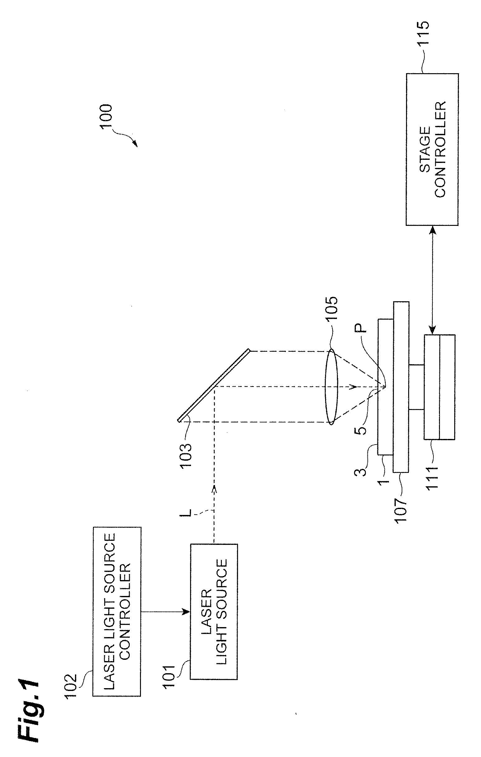
DESCRIPTION OF EMBODIMENTS
1 230 20 58 −172 2 230 20 90 −140 3 230 20 120 −110 4 230 20 158 −72 5 230 20 197 −33 6 230 20 235 +5 Example SD3 70 70 0 SD2 190 190 0 SD1 230 58 −172 Comparative SD3 70 70 0 Example SD2 190 190 0 SD1 230 230 0 Example SD3 70 70 0 SD2 190 190 0 SD1 230 230 0 * Provided that, an axicon lens pattern is used. Comparative SD3 70 70 0 Example SD2 190 190 0 SD1 230 230 0 Reference SD3 100 100 0 10 Example SD2 180 180 0 10 SD1 260 260 0 10 INDUSTRIAL APPLICABILITY
REFERENCE SIGNS LIST