Pressure Sensor
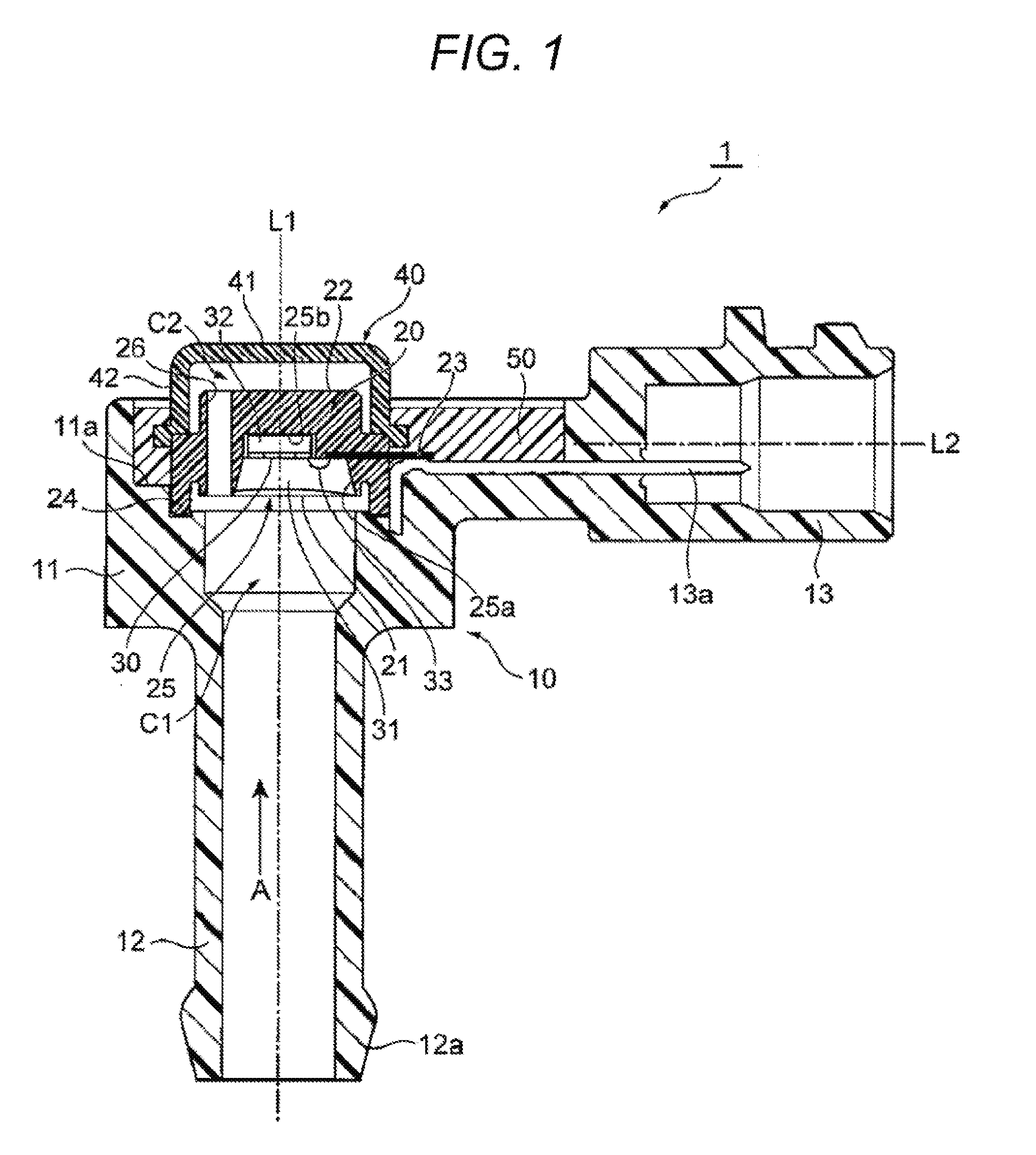
The present invention relates to a pressure sensor. Conventionally an invention relating to a semiconductor pressure sensor used for detection of intake pressure of an internal combustion engine, detection of atmospheric pressure or the like is known (see PTL 1 to be described below). This conventional semiconductor pressure sensor includes a sensor element, a printed circuit board, and a base. The sensor element has a pressure introduction pipe. The printed circuit board supports the sensor element to be spaced with a predetermined interval therebetween. The base holds the printed circuit board and has a pressure passage into which the pressure introduction pipe of the sensor element is inserted. A spacing distance between the sensor element and the printed circuit board is set such that a temperature decrease rate of the sensor element during natural cooling is lower than a temperature decrease rate of the pressure passage in the base (see claim 1 and With this configuration, the sensor element and the pressure introduction pipe are kept at a higher temperature than the pressure passage after the engine stops, the humidity of introduced air, which has been introduced into the pressure passage, the pressure introduction pipe, and a conversion unit that converts the pressure into an electric signal, is condensed first in the pressure passage having a low temperature. As a result, the humidity of the introduced air decreases so that it is possible to prevent condensation and freezing in the pressure introduction pipe and the conversion unit of the sensor element. Therefore, it is possible to obtain an excellent semiconductor pressure sensor which does not cause reduction in accuracy of pressure detection or a malfunction even in a low temperature operation such as restart of the internal combustion engine (see paragraphs 0012 and 0019, and the like of PTL 1). In addition, pressure sensor in which a pressure detection element is configured as a sensor chip is known (see paragraph 0029, The semiconductor pressure sensor described in PTL 1 can prevent the condensation in the sensor element, but has a problem that a degree of freedom in design is low so that it is not suitable for miniaturization. On the other hand, the pressure sensor described in PTL 2 can improve a degree of freedom in design as compared to the semiconductor pressure sensor described in PTL 1 by using the sensor chip as the pressure detection element, and thus, is suitable for miniaturization, which is advantageous. PTL 1: JP 11-118639 A PTL 2: JP 2010-19663 A In the pressure sensor described in PTL 2, the sensor chip is provided in a recess of a case, and a bonding wire or the like is coated by filling this recess with a protective member made of fluorine gel, fluorine rubber, or the like so as to prevent corrosion and the like (see paragraphs 0029 to 0031, The present invention has been made in view of the above problems, and an object thereof is to provide a pressure sensor that uses a sensor chip as a pressure measurement element and can suppress condensation around the sensor chip of water vapor permeating a protective member from a gas to be measured. In order to achieve the above-described object, the pressure sensor of the present invention including a pressure measurement chamber into which a gas to be measured is introduced, a sensor chip which faces the pressure measurement chamber, a sensor support which has a support surface supporting the sensor chip, and a protective member which covers the sensor chip, includes a heat insulation chamber which faces a back surface opposite to the support surface of the sensor support, and a gas passage which communicates with the heat insulation chamber and the pressure measurement chamber. In the pressure sensor of the present invention, the pressure of the gas to be measured introduced into the pressure measurement chamber can be measured by the sensor chip facing the pressure measurement chamber. In addition, a fluid to be measured is introduced into both the pressure measurement chamber facing the support surface of the sensor support and the heat insulation chamber facing the back surface of the sensor support via the gas passage communicating between the pressure measurement chamber and the heat insulation chamber, and it is possible to suppress temperature decreases of both the support surface and the back surface of the sensor support. Therefore, according to the pressure sensor of the present invention, the temperature of the protective member covering the sensor chip supported on the support surface of the sensor support is prevented from lowering to a temperature equal to or lower than a dew point of the gas to be measured, and it is possible to prevent water vapor permeating the protective member from the gas to be measured from being condensed around the sensor chip. Hereinafter, embodiments of a pressure sensor according to the present invention will be described with reference to the drawings. The pressure sensor 1 of the present embodiment can be used, for example, for measurement of intake pressure of an internal combustion engine and measurement of exhaust pressure. For example, the pressure sensor 1 can include: an exterior case 10; a sensor support 20 fixed to the exterior case 10; a sensor chip 30 supported by the sensor support 20; and a cover 40 covering the sensor support 20. For example, the exterior case 10 is manufactured by molding with a mold using a thermosetting resin such as an epoxy resin or a thermoplastic resin such as a polybutylene terephthalate (PBT) resin and a polyphenylene sulfide (PPS) resin as a material. For example, the exterior case 10 includes: a main body 11 which supports the sensor support 20; a pressure introduction pipe 12 which introduces a gas A to be measured into the main body 11; and a connector portion 13 connected to the main body 11. The main body 11 of the exterior case 10 is formed in a cylindrical shape having openings at both ends in a direction of an axis L1, for example. In the main body 11, the opening at one end in the direction of the axis L1 is connected to the pressure introduction pipe 12, and a pressure measurement chamber C1 is defined inside the opening. The pressure measurement chamber C1 faces the support surface 21 of the sensor support 20 supporting the sensor chip 30, and the gas A to be measured is introduced through the pressure introduction pipe 12. The main body 11 has a recess 11 The pressure introduction pipe 12 of the exterior case 10 is formed in a tubular shape having one end connected to an opening at a bottom of the main body 11 and the other end opened. The end on the opposite side of the end of the pressure introduction pipe 12 connected to the main body 11 has a tapered enlarged-diameter portion 12 For example, the connector portion 13 of the exterior case 10 extends in a direction of an axis L2 perpendicular to the direction of the axis L1 of the pressure introduction pipe 12 and the main body 11, and has one end connected to a side portion of the main body 11 and the other end having a substantially cylindrical shape with a protrusion on an outer circumference thereof. The connector portion 13 is connected to a connector portion of a wiring connected to, for example, an engine control unit (ECU) (not illustrated), and outputs an output signal of the sensor chip 30 to the ECU via a plurality of the connector pins 13 The connector pin 13 The sensor support 20 is manufactured, for example, by molding with a mold using the same resin material as the exterior case 10 as a material. The sensor support 20 is formed, for example, in a discoid shape or a cylindrical shape, and has a protruding portion 24 protruding in a radial direction from an outer circumferential surface and extending along the outer circumferential surface. In the pressure sensor 1 of the present embodiment, the sensor support 20 includes: the support surface 21 which supports the sensor chip 30; a back surface 22 opposite to the support surface 21; the connection terminal 23 insert-molded in the sensor support 20; the recess 25 provided in the support surface 21; and a gas passage 26 passing through the sensor support 20. The recess 25 provided in the support surface 21 of the sensor support 20 includes: a protective member accommodating recess 25 The sensor chip 30 is a semiconductor sensor made of, for example, silicon, and has a sensing unit that converts the pressure of the gas A to be measured into an electric signal. For example, the sensing unit can include a piezoelectric element or a strain gauge fixed to a diaphragm which is elastically deformed by the pressure of the gas A to be measured to form a bridge circuit. The sensor chip 30 is bonded to the glass pedestal 32 by, for example, anodic bonding such that the diaphragm of the sensing unit closes the recess provided in the glass pedestal 32. The glass pedestal 32 is fixed to the bottom of the sensor accommodating recess 25 The protective member accommodating recess 25 As the protective member 31, for example, a polymer material having excellent electrical insulating property and chemical resistance can be used. As the polymer material, for example, silicone gel, fluorine gel, or the like can be used. For example, after fixing the sensor chip 30 to the sensor accommodating recess 25 The gas passage 26 penetrates the sensor support 20 from the support surface 21 to the back surface 22, and communicates the pressure measurement chamber C1 facing the support, surface 21 of the sensor support 20 and a heat insulation chamber C2 facing the back surface 22 opposite to the support surface 21 of the sensor support 20. Although the single gas passage 26 is provided in the sensor support 20 in the example illustrated in The connection terminal 23 is, for example, a terminal made of phosphor bronze plated with nickel, is insert-molded on the sensor support 20, and extends in the radial direction of the sensor support 20 from the bottom of the protective member accommodating recess 25 The cover 40 is a lid-like or cap-like member that covers the back surface 22 opposite to the support surface 21 of the sensor support 20, and is a flat cylindrical member having a flat discoid upper wall 41 and a side wall 42 that hangs downward from a peripheral edge of the upper wall 41 along the direction of the axis L1 of the sensor support 20. A lower end of the side wall 42 of the cover 40 is supported by the protruding portion 24 of the sensor support 20 and is bent to the outer side in the radial direction of the cover 40. The cover 40 defines the heat insulation chamber C2 facing the back surface 22 of the sensor support 20. As the filler 50 filled in the recess 11 Hereinafter, functions of the pressure sensor 1 of the present embodiment will be described. As described above, the pressure sensor 1 of the present embodiment is used to measure the gas A to be measured such as intake air and exhaust gas of the internal combustion engine. In the pressure sensor 1, the pressure introduction pipe 12 provided in the exterior case 10 is connected to an intake pipe and an exhaust pipe via a tube and a connector, and the connector portion 13 provided in the exterior case 10 is connected to the connector portion 13 of the wiring connected to the ECU. The gas A to be measured such as intake air and an exhaust gas is introduced into the pressure measurement chamber C1 of the main body 11 of the exterior case 10 via the pressure introduction pipe 12 of the exterior case 10. The diaphragm of the sensing unit of the sensor chip 30 facing the pressure measurement chamber C1 is deformed due to the pressure of the gas A to be measured, which has been introduced into the pressure measurement chamber C1, and the electric signal in accordance with to the pressure of the gas A to be measured is output from the sensing unit. An output of the sensing section of the sensor chip 30 is output to the connector pin 13 The cover 40 of the pressure sensor 1 or the exterior case 10 is cooled by outside air taken in, for example, during traveling of a vehicle, and tends to become a temperature lower than a temperature of the gas A to be measured. In particular, when the vehicle performs high-speed traveling, and then, temporarily stops, and performs high-speed traveling again, the cooling function by the outside air increases in a state where the temperature of the gas A to be measured increases, and a temperature difference between the cover 40 of the pressure sensor 1 or the exterior case 10 and the gas A to be measured is likely to be large. In addition, during regeneration of a diesel particulate filter (DPF), the temperature of the gas A to be measured becomes higher than the temperature of the outside air, the temperature difference between the cover 40 of the pressure sensor 1 or the exterior case 10 and the gas A to be measured is likely to be large. In addition, when a polymer material is used as the protective member 31 covering the sensor chip 30 or the like, a liquid contained in the gas A to be measured can be blocked by the protective member 31, but the polymer material has a property of permeating water vapor. Thus, the water vapor contained in the gas A to be measured tends to be turned into a state of permeating the protective member 31. The pressure sensor 1X of the comparative example illustrated in The pressure sensor 1X of the comparative example illustrated in For example, when the temperature of the protective member 31 becomes significantly lower than the temperature of the gas A to be measured, for example, to fall below the dew point of the gas A to be measured in a state where water vapor permeates the protective member 31, condensation of water vapor permeating the protective member 31 causes electrolytic corrosion in the sensor chip 30, the wire 33, the connection terminal 23, and the connecting portion thereof covered with the protective member 31, which may result in malfunctioning or disconnection at the time of pressure measurement. In addition, if the temperature of the protective member 31 further drops below a freezing point depending on conditions such as the outside air temperature, there is a risk that moisture condensed inside the protective member 31 may freeze. Here, the pressure sensor 1 of the present embodiment is common to the pressure sensor 1X of the comparative example illustrated in Thus, the gas A to be measured, which has been introduced into the pressure measurement chamber C1 via the pressure introduction pipe 12, is introduced into the heat insulation chamber C2 by the gas passage 26 communicating the heat insulation chamber C2 facing the back surface 22 of the sensor support 20 and the pressure measurement chamber C1 facing the support surface 21 of the sensor support 20. The gas A to be measured, which has been introduced into the heat insulation chamber C2 keeps the back surface 22 of the sensor support 20 warm. That is, the sensor support 20 is kept warm or warmed by the gas A to be measured, which has been introduced into both of the pressure measurement chamber C1 facing the support surface 21 and the heat insulation chamber C2 facing the back surface 22 as both sides of the support surface 21 and the back surface 22 are covered with the gas A to be measured. As a result, even if the cooling effect of the cover 40 and the exterior case 10 according to the outside air increases, or the temperature difference between the outside air and the gas A to be measured increases as described above, it is possible to suppress the temperature of the sensor support 20 from being lower than the dew point of the gas A to be measured or greatly lower than the temperature of the gas A to be measured. Therefore, it is possible to suppress water vapor permeating the protective member 31 from the gas A to be measured from being condensed around the sensor chip 30, and to prevent the freezing of moisture inside the protective member 31. In the pressure sensor 1 of the present embodiment, the gas passage 26 that communicates the pressure measurement chamber C1 and the heat insulation chamber C2 is provided in the sensor support 20. Therefore, it is possible to form the gas passage 26 with hardly changing the design of the exterior case 10. In addition, the pressure sensor 1 of the present embodiment includes the pressure introduction pipe 12 introducing the gas A to be measured, and the pressure introduction pipe 12 is connected to the pressure measurement chamber C1. As a result, it is possible to reduce a pressure loss of the gas A to be measured which is introduced into the pressure measurement chamber C1 and to measure the pressure of the gas A to be measured with higher accuracy. In addition, in the pressure sensor 1 of the present embodiment, the sensor chip 30 is connected to the connection terminal 23, which forms an output terminal together with the connector pin 13 In addition, the material of the protective member 31 is the polymer material in the pressure sensor 1 of the present embodiment. Thus, the water vapor contained in the gas A to be measured permeates the protective member 31, but it is possible to prevent the condensation of the water vapor permeating the protective member 31 by suppressing the temperature decrease of the protective member 31 and to prevent the freezing of moisture condensed in the protective member 31 according to the pressure sensor 1 of the present embodiment. As described above, according to the pressure sensor 1 of the present embodiment, it is possible to suppress the water vapor permeating the protective member 31 from the gas A to be measured from being condensed around the sensor chip 30 using the sensor chip 30 as a pressure measurement element, and to prevent trouble and disconnection at the time of pressure measurement. The pressure sensor 1A of the present embodiment is different from the pressure sensor 1 of the first embodiment illustrated in The pressure sensor 1A of the present embodiment includes the pressure introduction pipe 12 which introduces the gas A to be measured, and the pressure introduction pipe 12 is connected to the heat insulation chamber C2 defined by the main body 11 of the exterior case 10. Thus, the gas A to be measured, which has been introduced into the main body 11 of the exterior case 10 via the pressure introduction pipe 12, is first introduced into the heat insulation chamber C2 defined by the main body 11, and thereafter, is introduced into the pressure measurement chamber C1 defined by the cover 40 via the gas passage 26 provided in the sensor support 20. As a result, moisture, foreign matters, and the like contained in the gas A to be measured are prevented from adhering to the protective member 31 that covers the sensor chip 30, and the durability of the pressure sensor 1A is improved. In addition, the pressure sensor 1A of the present embodiment is warmed or kept warm by the gas A to be measured, which has been introduced into the pressure measurement chamber C1 and the heat insulation chamber C2, as both sides of the support surface 21 and the back surface 22 of the sensor support 20 are covered with the gas A to be measured, which is similar to the pressure sensor 1 of the first embodiment described above. Therefore, it is possible to obtain the same effect as the pressure sensor 1 of the first embodiment according to the pressure sensor 1A of the present embodiment. The pressure sensor 1B of the present embodiment is different from the pressure sensor 1 of the first embodiment illustrated in The pressure sensor 1B according to the present embodiment includes the exterior case 10 that supports the sensor support 20, and the gas passage 14 that communicates the pressure measurement chamber C1 and the heat insulation chamber C2 is provided in the exterior case 10. As a result, it is possible to form the gas passage 14 in the pressure sensor 1B with hardly changing the design of the sensor support 20. In addition, both sides of the support surface 21 and the back surface 22 of the sensor support 20 are covered with the gas A to be measured, and are warmed or kept warm by the gas A to be measured, which has been introduced into the pressure measurement chamber C1 and the heat insulation chamber C2 in the pressure sensor 1B of the present embodiment, which is similar to the pressure sensor 1 of the first embodiment described above. Therefore, it is possible to obtain the same effect as the pressure sensor 1 of the first embodiment according to the pressure sensor 1B of the present embodiment. The pressure sensor 1C of the present embodiment is different from the pressure sensor 1B of the second embodiment illustrated in In the pressure sensor 1C of the present embodiment, the main body 11 of the exterior case 10 has an opening 15 in a side portion, and has a groove portion 16 which fits the end portion of the side wall 42 of the cover 40 to the periphery of the opening 15. The cover 40 is fixed to the exterior case 10 by fitting the end portion of the side wall 42 to the groove 16 of the exterior case 10 filled with, for example, an epoxy resin and curing the epoxy resin, and closes the opening 15 in the side portion of the main body 11 and defines the pressure measurement chamber C1 inside the opening 15 in the side portion of the main body 11. A support portion 17, which supports the sensor support 20 on the exterior case 10 is provided inside the opening 15 of the main body 11 of the exterior case 10 in such a manner that the direction of the axis L3 of the sensor support 20 is perpendicular to the direction of the axis L1 of the pressure introduction pipe 12. The support portion 17 has an opening 17 In addition, the connector portion 13, not illustrated in In the pressure sensor 1C according to the present embodiment, the pressure introduction pipe 12 is connected to the heat insulation chamber C2 defined by the main body 11 in parallel with the back surface 22 of the sensor support 20. As a result, it is possible to prevent moisture and foreign matters contained in the gas A to be measured from colliding with the back surface 22 of the sensor support 20, thereby further improving the durability of the pressure sensor 1C. In addition, in the pressure sensor 1C of the present embodiment, both the support surface 21 and the back surface 22 of the sensor support 20 are covered and warmed or kept warm by the gas A to be measured introduced into the heat insulation chamber C2 via the pressure introduction pipe 12 and the gas A to be measured introduced from the heat insulation chamber C2 into the pressure measurement chamber C1 via the gas passage 14, which is similar to the pressure sensor 1B of the second embodiment. Therefore, it is possible to obtain the same effect as the pressure sensor 1B of the second embodiment according to the pressure sensor 1C of the present embodiment. Although the embodiment of the present invention has been described in detail with reference to the drawings as above, a specific configuration is not limited to the embodiment, and design alterations or the like made in a scope not departing from a gist of the present invention is included in the present invention. 1, 1A, 1B, 1C pressure sensor 10 exterior case 12 pressure introduction pipe 14 gas passage 20 sensor support member 21 support surface 22 back surface 23 connection terminal (output terminal) 26 gas passage 30 sensor chip 31 protective member 33 wire A gas to be measured C1 pressure measurement chamber C2 heat insulation chamber Provided is a pressure sensor that uses a sensor chip as a pressure measurement element and can suppress condensation around the sensor chip of water vapor permeating a protective member from a gas to be measured. The pressure sensor includes a pressure measurement chamber into which a gas to be measured is introduced; a sensor chip that faces the pressure measurement chamber; a sensor support that has a support surface supporting the sensor chip; and a protective member that covers the sensor chip. The pressure sensor also includes a heat insulation chamber that faces a back surface opposite to the support surface of the sensor support; and a gas passage that communicates the heat insulation chamber and the pressure measurement chamber. 1. A pressure sensor including a pressure measurement chamber into which a gas to be measured is introduced, a sensor chip which faces the pressure measurement chamber, a sensor support which has a support surface supporting the sensor chip, and a protective member which covers the sensor chip, the pressure sensor comprising:
a heat insulation chamber which faces a back surface opposite to the support surface of the sensor support; and a gas passage which communicates the heat insulation chamber and the pressure measurement chamber. 2. The pressure sensor according to The pressure sensor according to an exterior case which supports the sensor support, wherein the gas passage is provided in the exterior case. 4. The pressure sensor according to a pressure introduction pipe which introduces the gas to be measured, wherein the pressure introduction pipe is connected to the pressure measurement chamber. 5. The pressure sensor according to a pressure introduction pipe which introduces the gas to be measured, wherein the pressure introduction pipe is connected to the heat insulation chamber. 6. The pressure sensor according to 7. The pressure sensor according to the protective member covers the wire. 8. The pressure sensor according to TECHNICAL FIELD
BACKGROUND
CITATION LIST
Patent Literature
SUMMARY OF INVENTION
Technical Problem
Solution to Problem
Advantageous Effects of Invention
BRIEF DESCRIPTION OF DRAWINGS
DESCRIPTION OF EMBODIMENTS
First Embodiment
Second Embodiment
Third Embodiment
Fourth Embodiment
REFERENCE SIGNS LIST