DUAL-STRUCTURED ELECTRIC DRIVE AND POWER SYSTEM FOR HYBRID VEHICLES
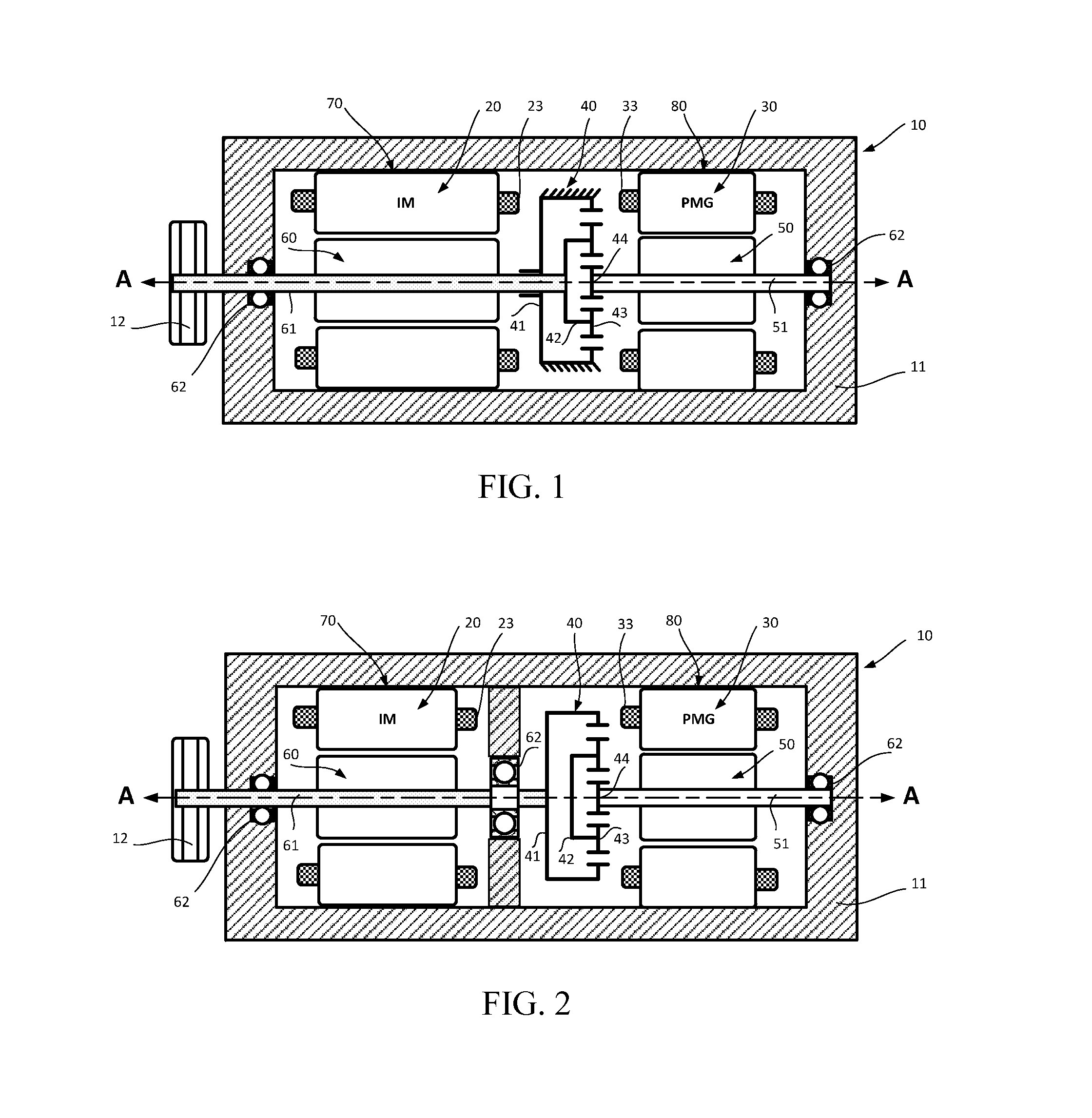
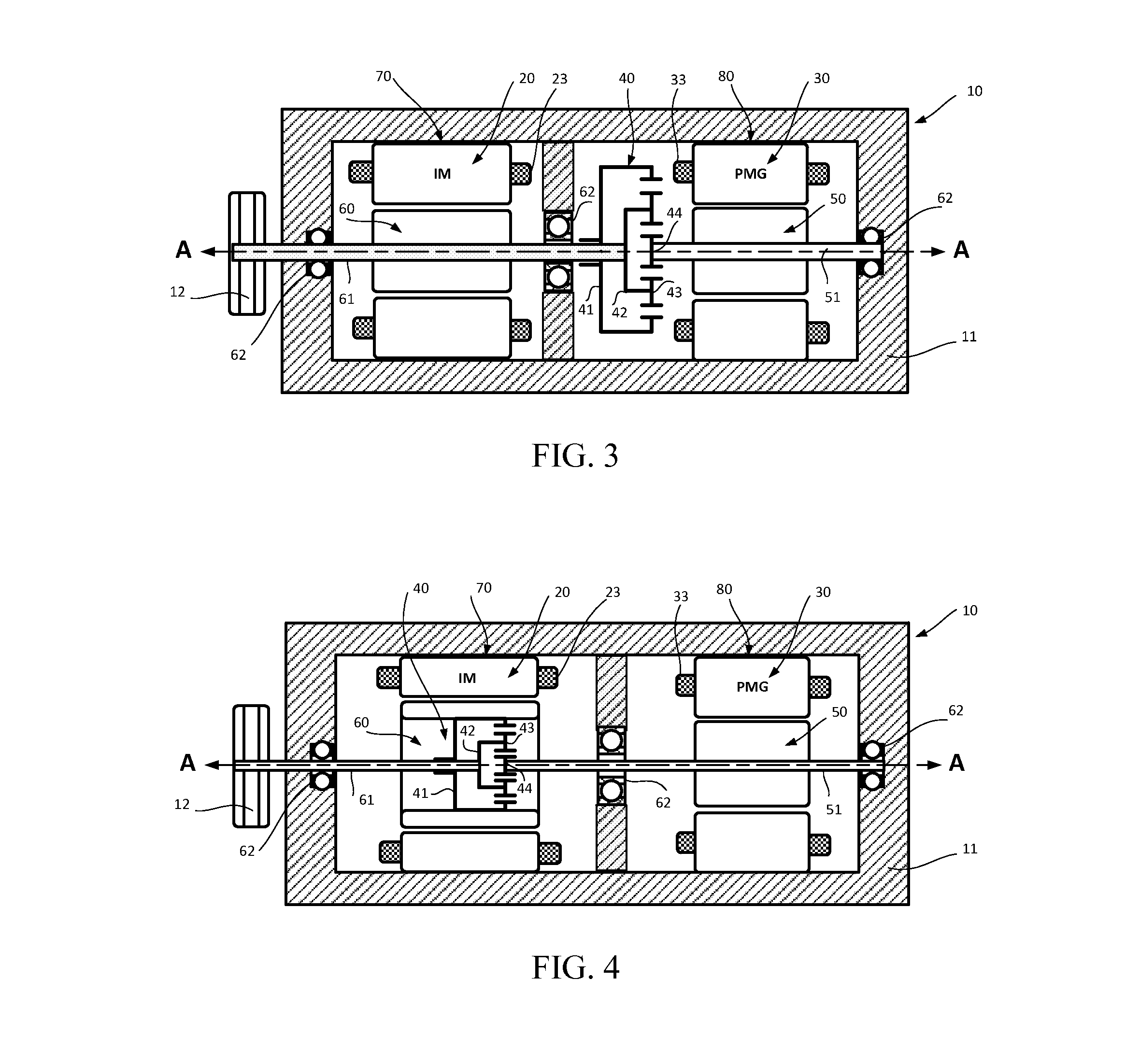
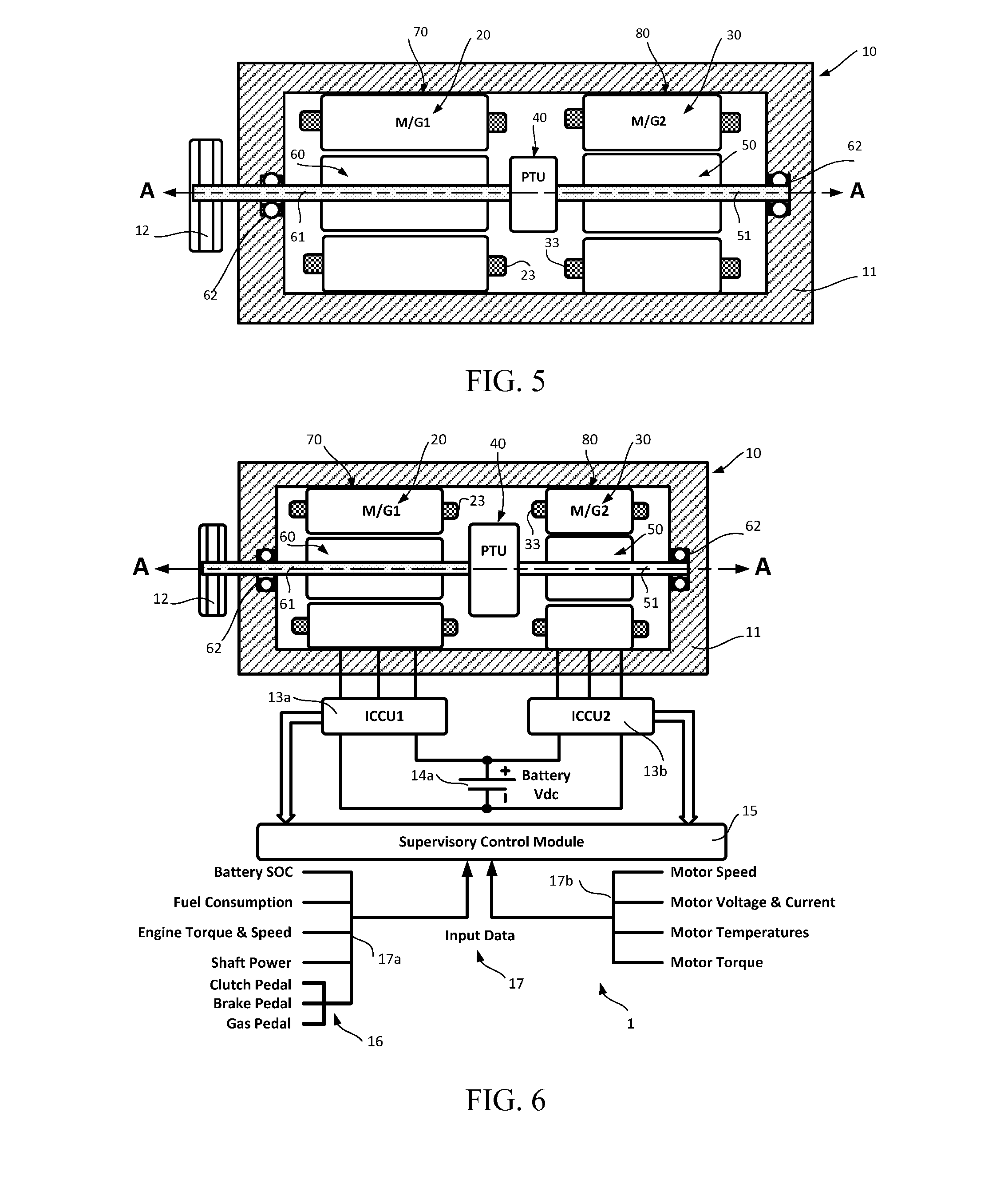
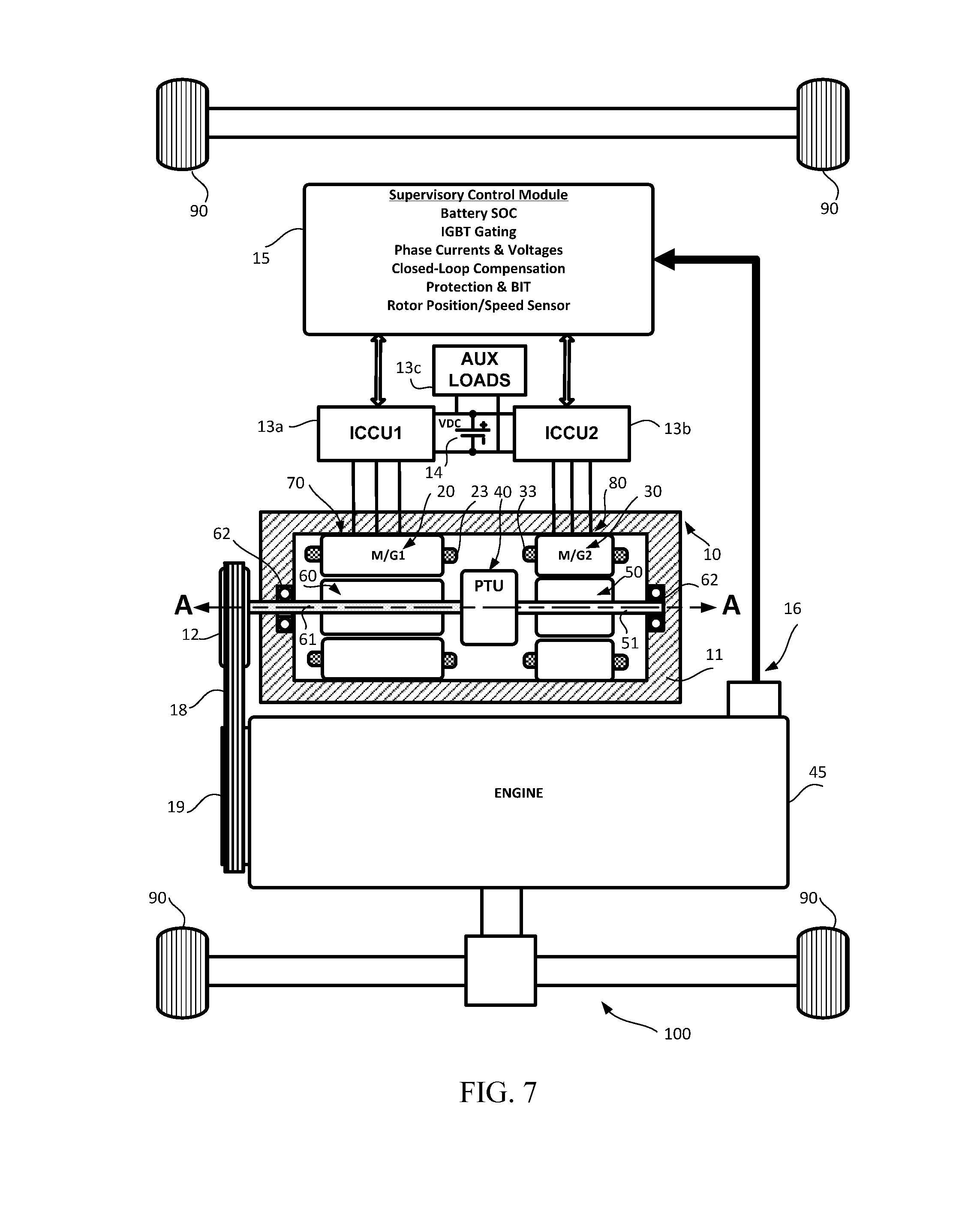
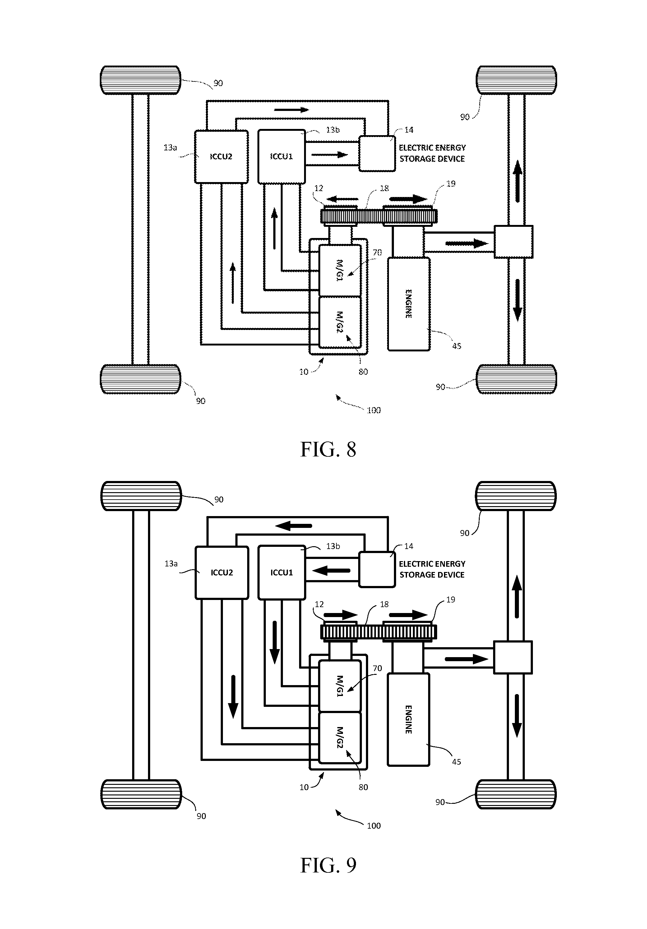
This application claims the benefits of the U.S. Provisional Application No. 61/741,763, filed on Jul. 17, 2012. The disclosure of the Provisional Application is incorporated herein by reference in its entirety for any and all purposes. The present invention pertains to power-assist parallel hybrid vehicles. More specifically, the present invention pertains to a dual-structured power output apparatus that provides a means for outputting both mechanical power and electrical power with high efficiency and is capable of improving fuel efficiency of the prior art hybrid vehicle, as well as to an electric drive and power system and a method of controlling the power output apparatus. In recent years, the trend in the development of fuel-efficient and low emission hybrid vehicle powertrain technologies that combine a conventional combustion engine (ICE) with an electric propulsion system has increased significantly. Among the roughly four main categories: series, parallel, series-parallel and mild hybrid vehicle technologies on the market today, the mild hybrid technology is the least expensive and affordable. The technology is relatively less complex and can be readily retrofitted into an existing conventional vehicle with little or no modifications. It involves replacing the conventional alternator with an over-sized belt-driven electric motor that is commonly referred to as a Belt Alternator Starter (BAS). The motor is coupled to the engine via a serpentine belt so that it serves as both a generator and starter. This permits a low-cost method of adding hybrid capabilities to a conventional vehicle, such as start-stop function as well as mild levels of torque assist and regenerative braking efficiency-improvement technology, that achieves about 15-20 percent improvement in fuel economy in urban driving. However, the authors of the present invention have recognized a number of functional drawbacks with the current state-of-the-art in belt-driven electric motor as typically utilized in mild hybrid vehicle powertrain technology on the market today. One functional drawback is that using a single electric motor makes it necessary for frequent mode reversals because it can operate only in one mode (motoring or generating) at a time, and this results in reduced powertrain performance and fuel efficiency. Typically, the electric motor operates in a limited mechanical torque- and power-assist modes for shorter durations and generating mode producing electrical power for longer durations in order to avoid depleting the onboard energy storage devices (super-capacitors and battery bank) of a hybrid vehicle. This operating limitation results in smaller improvement in fuel efficiency. Another functional drawback of the current state-of-the-art in belt-driven electric motors as utilized in mild hybrid vehicle powertrain technology is that they are typically optimized for one of the operating modes than the other. Therefore, in a hybrid powertrain that has such an electric motor mounted thereon, in a time period when the power demand requires the electric motor to operate in its less optimized mode, a reduced powertrain performance and fuel efficiency are achieved. Yet another functional drawback of the current state-of-the-art in belt-driven electric motors as utilized in mild hybrid vehicle powertrain technology is that the electric motors are typically sized based on the peak power. As a result, they are relatively over-sized, heavier and less efficient in the power range corresponding to the average power demand of the drive cycle. This is done in order to be able to support start-stop features during engine idle, regenerative braking during stopping and coasting, and engine mechanical power boosting and augmentation for transient power requirements. Therefore, in a vehicle that has such an electric motor mounted thereon, in a time period when the vehicle power demand in accordance with the driving conditions requires the electric motor to operate close to the average power demand, a reduced electric motor performance and fuel efficiency are achieved. A number of prior arts, for example U.S. Pat. No. 8,412,396, U.S. Pat. No. 5,943,918, U.S. Pat. No. 8,225,608, US2005/0,107,198, US2004/0,040,810 A1, U.S. Pat. No. 7,753,147, U.S. Pat. No. 7,914,416, and US2013/0,005,529 A1, have described a variety of hybrid vehicles comprising single and dual electric motor-generators. However, all of these prior art patents do not address any of the drawbacks discussed above in order to improve fuel efficiency of a belt-driven parallel hybrid vehicle. The apparatus disclosed in the present invention differs significantly from those disclosed in the prior arts in terms of its characteristics and method of control. Furthermore, no prior art in hybrid vehicle powertrain technologies and conversion of conventional vehicle into hybrid that use belt-driven electric motors coupled to the engine crankshaft via a special belt has provided solutions that address the functional drawbacks discussed above in order to achieve improvement in fuel efficiency. Accordingly, there is a need for a simple, cost-effective and affordable hybrid vehicle powertrain technology solution that provides further improvement in fuel efficiency of the prior art mild hybrid vehicle. Disclosed in the present invention is a dual-structured power output apparatus of an electric drive and power system that is capable of improving the fuel efficiency of the prior art hybrid vehicle. It comprises dual motor/generators having two stator assemblies, two rotor assemblies and a power transmission unit (PTU) enclosed in a single compact housing. The power transmission unit is disposed between the two motor/generators and coupled on both ends to the rotating shafts of the two rotor assemblies such that they may be rotatable at the same speed or relative to each other at different speeds with respect to the main housing. The power transmission unit of the dual-structured power output apparatus may be constructed as a planetary gear train mechanism, or a belt drive and pulley mechanism, or an electromechanical control mechanism. A single stage planetary gear train mechanism is utilized as an exemplary embodiment of the power transmission unit to describe the embodiments of the dual-structured power output apparatus of the present invention. In the dual-structured power output apparatus of the embodiments of the present invention, the planetary gear train mechanism includes a sun gear member, a planet carrier member and a ring gear member, and is disposed axially between the two motor/generators. The planetary gear train mechanism provides a mechanical means to increase the rotational speed of one of the electric motor/generators so that its physical size and weight are significantly reduced, and thereby resulting in reduction in the overall weight and size of the apparatus as well as improved power density and capability. In a similar manner, a pulley and timing belt mechanism or an electromechanical control mechanism may be utilized as a means for increasing the rotational speed of at least one of the electric motor/generators in order to reduce physical weight and size, and improve power density and capability. The dual-structured power output apparatus is coupled to the engine of a hybrid vehicle powertrain via a serpentine belt, a drive pulley attached to one of its shaft and a crankshaft pulley to construct a parallel-structured hybrid vehicle powertrain. This parallel structure of a hybrid vehicle powertrain provides a means whereby the mechanical power transmitted to a drivetrain is generated by both an engine and the dual-structured power output apparatus in order to maximize fuel economy. In accordance with the embodiments of the present invention, each of the motor/generators can function in either motoring or generating modes. The operating modes of the motor/generators are determined in accordance with the instantaneous driving conditions or state of a hybrid vehicle powertrain, and controlled based on the allocation of the electrical power to charge onboard electric energy storage devices (super-capacitors and battery bank) and mechanical torque and power to assist the engine in such a manner that improvement in fuel efficiency is achieved. Also, disclosed is an electric drive and power system including a dual-structured power output apparatus, two bidirectional inverter/converter control units (ICCUs), a supervisory control module (SCM) and onboard electric energy storage devices. The dual-structured power output apparatus comprises two motor/generators having two rotor assemblies that may be rotatable at the same speed on a common shaft, or may include a planetary gear train mechanism disposed adjacent to the motor/generators for improved power density and capability. The planetary gear train mechanism includes at least a ring gear member, a planet carrier member and a sun gear member. The planetary gear train mechanism may be mechanically coupled on both ends to the rotor shafts of the two motor/generators such that they rotate relative to each other at different speeds with respect to the main housing. The SCM monitors and provides commands for executing protection functions as well as the overall electrical power and mechanical power balance between the two motor/generators, the onboard electric energy storage devices and engine in accordance with the various driving conditions of a hybrid vehicle powertrain such that the overall fuel efficiency is improved. Meanwhile, the ICCUs simultaneously drive and control the two motor/generators to operate in motoring or generating mode as directed by the SCM. Also, disclosed in the present invention is a hybrid vehicle powertrain with the electric drive and power system mounted thereon that takes advantage of the characteristics of the dual-structured power output apparatus to achieve improvement in fuel efficiency. Also, further disclosed in the present invention is a method for controlling the power balance during various conditions between the dual-structured power output apparatus and ICCUs, onboard electric energy storage devices and engine so that the performance of the hybrid vehicle powertrain is optimized to achieve improved fuel efficiency. The following descriptions should not be considered limiting in any way. With reference to the accompanying drawings, like elements are numbered alike: In order to solve the functional drawbacks discussed above with the current state-of-the-art in belt-driven electric motors as utilized in power-assist parallel hybrid vehicle powertrain technology on the market today is to provide a dual-structured power output apparatus, which when incorporated into the powertrain of a hybrid vehicle or retrofitted into a conventional combustion engine vehicle, can achieve substantial improvement in the fuel efficiency. Hereafter, the embodiments of the present invention will be described referring to the accompanying drawings that include a single stage planetary gear train mechanism as an exemplary embodiment of the power transmission unit. Accordingly, the first object of the present invention is directed to a dual-structured power output apparatus, which no prior art has discussed, that comprises two electric motor/generators in tandem; and a planetary gear train mechanism that is axially disposed between the two motor/generators and includes a sun gear member, a planet carrier member and a ring gear member. The second object of the present invention is to provide a control system for controlling the operating modes as well as output mechanical power and electrical power of the two electric motor/generators. The third object of the present invention is to provide a method for controlling the output mechanical power and electrical power balance between the two electric motor/generators, the onboard electric energy storage devices and engine during various conditions of a hybrid vehicle powertrain in order to improve fuel efficiency. A detailed description of one or more embodiments of the disclosed apparatus is presented herein by way of exemplification and not limitation with reference to the Figures. It should be understood that although a hybrid power train has been used to describe one preferable application, the example dual-structured power output apparatus illustrated in the embodiments of the present invention could be used in other applications. The function of the planetary gear train mechanism 40 in the embodiments of the present invention is primarily to function as a power transfer mechanism to receive a rotational speed and torque (or mechanical power) from the rotor 60 of the first motor/generator M/G1 assembly 70 and transmit it to the rotor 50 of the second motor/generator M/G2 assembly 80 in such a manner that the torque and rotational speed are changed in accordance with the mechanics of planetary gear train. The connection arrangements of the ring gear member 41, planet carrier member 42 and sun gear 44 of the planetary gear train mechanism 40 serve to increase the rotational speed of the rotor 50 of the second motor/generator M/G2 assembly 80 based on the rotational speed of the rotor 60 of the first motor/generator M/G1 assembly 70. Thus, increasing the rotational speed of the rotor of the second motor/generator M/G2 assembly 80 makes it possible to significantly reduce the size (diameter or axial length) of the second motor/generator assembly 80 for the transmitted mechanical power, and thereby reducing the overall weight and physical size of the apparatus assembly 10 and improved power density and capability. Furthermore, the planetary gear train mechanism 40 may be disposed to effectively utilize the radial inner space provided radially inwardly of the axially extending stator coils 23 and 33 of the first motor/generator M/G1 assembly 70 and second motor/generator M/G2 assembly 80, whereby the required overall axial dimension of the power output apparatus assembly 10 can be reduced. In essence, the technique disclosed in the present invention of increasing the rotational speed of the rotor 50 of the second motor/generator M/G1 assembly 80 using a planetary gear train mechanism 40 effectively disposed axially in the radial inner space provided radially inwardly of the axially extending stator coils 23 and 33 makes it possible to significantly reduce the overall axial dimension of the power apparatus assembly 10, thus ensuring improved power density and capability essential for improving the fuel economy of a parallel hybrid vehicle. Referring now to The dual-structured power output apparatus of the first embodiment of the present invention in In Equations (1) and (4), the “±” (plus and minus) sign presents the direction of a motor/generator applied torque such that a “+” (plus) sign denotes motoring mode torque that is applied in the direction of rotation of the rotor shaft, and a “−” (minus) sign denotes generating mode torque that is applied in the reverse direction of rotation of the rotor shaft; Ωsh1 represents the rotational speed of the rotor shaft 61 of the first motor/generator M/G1 70; Ωsh2 represents the rotational speed of the rotor shaft 51 of the second motor/generator M/G2 80; Ωec represents the rotational speed of the engine 45 crankshaft pulley 19. Meanwhile, TMG1represents the torque applied by the first motor/generator M/G1 assembly 70 and, depending on its sign, it is transmitted to the crankshaft pulley 19 as positive or negative amount of torque assist by which the engine-produced torque is reduced or increased; Tsh1 represents the torque applied to the rotor shaft 61 and is equal to the torque TMG1applied by the first motor/generator M/G1 assembly 70; and Tsh2 represents the torque transmitted to the sun gear and rotor shaft 51 due to the rotor shaft 61 torque Tsh1. Meanwhile, ε represents the gear ratio, as expressed below in Equation (5), of the number of teeth of the ring gear member 41 to that of the sun gear member 44. This ratio is always greater than 1. Also, α denotes the pulley drive ratio, as defined in Equation (6), and is defined as the ratio of the outer pitch diameter of the crankshaft pulley 19 to that of the pulley 12 of the apparatus assembly 10. This ratio is typically between 1 and 3. In accordance with Equation (4), the sun gear member 44 and the connected rotor shaft 51 of the second motor/generator M/G2 assembly 80 rotate at a higher speed than the assembly 10 pulley 12 and the rotor shaft 61 of the first motor/generator M/G1 assembly 70. As a result, the size of second motor/generator M/G2 assembly required to match the required power demand is significantly reduced. Thus, as described earlier, the function of the planetary gear train mechanism 40 in the embodiments of the present invention is to increase the rotational speed of the sun gear 44 and rotor shaft 51 of the second motor/generator M/G2 assembly 80 so that its size is significantly reduced, resulting in reduction of the overall weight and physical size of the apparatus, which in turn ensures improved power density and capability. In other words, the planetary gear train mechanism 40 is arranged to primarily function as a power transfer mechanism to receive a rotational speed and torque (that is mechanical power) from the first motor/generator M/G1 assembly 70 and transmit it to the second motor/generator M/G2 assembly 80 in such a manner that the torque is scaled down and rotational speed is scaled up in accordance with planetary gear train mechanics to maintain the mechanical power. Specifically, the planetary gear mechanism is serving to transfer the mechanical power provided by the first motor/generator M/G1 assembly 70 by increasing the rotational speed and decreasing the torque of the second motor/generator M/G2 assembly 80 in accordance with the mechanics of planetary gear train as given in Equations (1) through (4). Accordingly, the size of the second motor/generator M/G2 assembly 80 required to match the mechanical power transferred from the rotor shaft 61 of the first motor/generator M/G1 assembly 70 is smaller than the size of the first motor/generator M/G1 assembly 70. Therefore, the second motor/generator M/G2 assembly 80 is constructed to have a smaller size than the first motor/generator M/G1 assembly 70, thereby significantly reducing the overall physical size and weight of the apparatus and ensuring improved power density and capability. In summary, the technique disclosed in this embodiment of the present invention of increasing the speed of the rotor 50 of the second motor/generator M/G1 assembly 80 using a planetary gear train mechanism 40 effectively disposed axially in the radial inner space provided radially inwardly of the axially extending stator coils 23 and 33 makes it possible to significantly reduce the overall axial dimension of the power apparatus assembly 10, thus ensuring improved power density and capability essential for improving the fuel economy of a parallel hybrid vehicle. For stable operation of this embodiment of the dual-structured power output apparatus assembly 10 of When it is determined by a concrete procedure of the SCM 15 that the driving mode of the hybrid vehicle powertrain 100 in When it is determined by a concrete procedure of the SCM 15 that the driving mode of the hybrid vehicle powertrain 100 in When it is determined by a concrete procedure of the SCM 15 that the driving mode of the hybrid vehicle powertrain 100 in A dual-structured power output apparatus in a second embodiment of the present invention is discussed below. In Equations (10) through (14), the “±” (plus and minus) sign presents the direction of a motor/generator applied torque such that a “+” (plus) sign denotes motoring mode torque that is applied in the direction of rotation of the rotor shaft, and a “−” (minus) sign denotes generating mode torque that is applied in the reverse direction of rotation of the rotor shaft; TMG1represents the torque applied by the first motor/generator M/G1 assembly 70 and, depending on its sign, it is transmitted to the crankshaft pulley 19 as positive or negative amount of torque assist by which the engine-produced torque is reduced or increased; TMG2represents the torque applied by the second motor/generator M/G2 assembly 80 and, depending on its sign, it is transmitted to the crankshaft pulley 19 as positive or negative amount of torque assist by which the engine-produced torque is reduced or increased; Tsh1 represents the torque applied to the rotor shaft 61 and is equal to the torque applied by the first motor/generator M/G1 assembly 70; Tpc represents the torque transmitted to the planet carrier member 42 due to the rotor shaft 61 torque Tsh1; and Tsh2 represents the torque transmitted to the sun gear 44 and rotor shaft 51 due to the rotor shaft 61 torque Tsh1. Meanwhile, Ωsh2 represents the rotational speed of the sun gear member 44 and rotor shaft 51; Ωsh1 represents the rotational speed of the rotor shaft 61 of the first motor/generator M/G1 assembly 70 and the assembly 10 pulley 12; Ωpcrepresents the rotational speed of the planet carrier member 42; and Ωecrepresents the engine 45 crankshaft pulley 19 rotational speed. The gear ratio ε is as defined in Equation (5) and pulley drive ratio α is as defined in Equation (6). As described earlier, the planetary gear train mechanism 40 is arranged to primarily function as a power transfer mechanism to receive a rotational speed and torque (that is mechanical power) from the first motor/generator M/G1 assembly 70 and transmit it to the second motor/generator M/G2 assembly 80 in such a manner that the torque is scaled down and rotational speed is scaled up in accordance with planetary gear train mechanics to maintain the mechanical power. Specifically, the planetary gear mechanism is serving to transfer the mechanical power provided by the first motor/generator M/G1 assembly 70 by increasing the rotational speed and decreasing the torque of the second motor/generator M/G2 assembly 80 in accordance with the mechanics of planetary gear as given in Equations (10) through (14). Accordingly, the size of the second motor/generator M/G2 assembly 80 required to match the mechanical power transferred from the rotor shaft 61 of the first motor/generator M/G1 assembly 70 is smaller than the size of the first motor/generator M/G1 assembly 70. Therefore, the second motor/generator M/G2 assembly 80 is constructed to have a smaller size than the first motor/generator M/G1 assembly 70, thereby significantly reducing the overall physical size and weight of the apparatus and ensuring improved power density and capability. In essence, the technique disclosed in this embodiment of the present invention of increasing the rotational speed of the rotor 50 of the second motor/generator M/G1 assembly 80 using a planetary gear train mechanism effectively disposed axially in the radial inner space provided radially inwardly of the axially extending stator coils 33 and 23 makes it possible to significantly reduce the overall axial dimension of the power apparatus assembly 10, thus ensuring improved power density and capability essential for improving the fuel economy of a parallel hybrid vehicle. One aspect of the second embodiment of the present invention is that the rotational speed Ωpcof the planet carrier member 42 is not set and it depends on the rotating speeds of the ring gear 41 and sun gear 44 members. Based on the rotational speed relationship given in Equation (14), the determination of the rotating speeds of any of the two gear members automatically results in setting the rotating speed of the remaining planetary gear member. In essence, this provides one degree of freedom to set the rotating speed and mechanical power of the sun gear 44, and hence the rotating speed of the second motor/generator M/G2 assembly 80 rotor shaft 51. For a given engine torque and speed, a preferable choice is the rotating speed that gives the maximum possible efficiency, thereby enhancing the efficiency of the whole apparatus. Dynamic equilibrium of the first motor/generator M/G1 assembly 70 applied torque TMG1and second motor/generator M/G2 assembly 80 applied torque TMG2is essential for stable operation. This is accomplished by satisfying the torque and speed relationships given in Equations (10) through (14). When it is determined by a concrete procedure of the SCM 15 that the driving mode of the hybrid vehicle powertrain 100 in When it is determined by a concrete procedure of the SCM 15 that the driving mode of the hybrid vehicle powertrain 100 in When it is determined by a concrete procedure of the SCM 15 that the driving mode of the hybrid vehicle powertrain 100 in A dual-structured power output apparatus in a third embodiment of the present invention is discussed below. In Equations (18) through (22), the “±” (plus and minus) sign presents the direction of a motor/generator applied torque such that a “+” (plus) sign denotes motoring mode torque that is applied in the direction of rotation of the rotor shaft, and a “−” (minus) sign denotes generating mode torque that is applied in reverse direction of rotation of the rotor shaft; TMG1represents the torque applied by the first motor/generator M/G1 assembly 70 and, depending on its sign, it is transmitted to the crankshaft pulley 19 as positive or negative amount of torque assist by which the engine-produced torque is reduced or increased; in a similar manner, TMG2represents the torque applied by the second motor/generator M/G2 assembly 80 and, depending on its sign, it is transmitted to the crankshaft pulley 19 as positive or negative amount of torque assist by which the engine-produced torque is reduced or increased; Tsh1 represents the torque applied to the rotor shaft 61 and is equal to the torque applied by the first motor/generator M/G1 assembly 70; Tpr represents the torque transmitted to the ring gear member 41 due to the rotor shaft 61 torque Tsh1; and Tsh2 represents the torque transmitted to the sun gear 44 and rotor shaft 51 due to the shaft 61 torque Tsh1. Meanwhile, Ωnsh2 represents the rotational speed of the sun gear member 44 and rotor shaft 51; Ωsh1 represents the rotational speed of the rotor shaft 61 of the first motor/generator M/G1 assembly 70 and the assembly 10 pulley 12; Ωprrepresents the rotational speed of the planet carrier member 42; and Ωecrepresents the engine 45 crankshaft pulley 19 rotational speed. The gear ratio ε is as defined earlier in Equation (5) and pulley drive ratio α is as defined in Equation (6). As described earlier, the planetary gear train mechanism 40 is arranged to primarily function as a power transfer mechanism to receive a rotational speed and torque (that is mechanical power) from the first motor/generator M/G1 assembly 70 and transmit it to the second motor/generator M/G2 assembly 80 in such a manner that the torque is scaled down and rotational speed is scaled up in accordance with planetary gear train mechanics to maintain the mechanical power. Specifically, the planetary gear mechanism is serving to transfer the mechanical power provided by the first motor/generator M/G1 assembly 70 by increasing the rotational speed and decreasing the torque of the second motor/generator M/G2 assembly 80 in accordance with the mechanics of planetary gear as given in Equations (18) through (22). Accordingly, the size of the second motor/generator M/G2 assembly 80 required to match the mechanical power transferred from the rotor shaft 61 of the first motor/generator M/G1 assembly 70 is smaller than the size of the first motor/generator M/G1 assembly 70. Therefore, the second motor/generator M/G2 assembly 80 is constructed to have a smaller size than the first motor/generator M/G1 assembly 70, thereby significantly reducing the overall physical size and weight of the apparatus and ensuring improved power density and capability. In essence, the technique disclosed in this embodiment of the present invention of increasing the rotational speed of the rotor 50 of the second motor/generator M/G1 assembly 80 using a planetary gear train mechanism effectively disposed axially in the radial inner space provided radially inwardly of the axially extending stator coils 23 and 33 makes it possible to significantly reduce the overall axial dimension of the power apparatus assembly 10, thus ensuring improved power density and capability essential for improving the fuel economy of a parallel hybrid vehicle. One aspect of this embodiment of the present invention is that the speed Ωprof the ring gear 41 is not set and it depends on the rotating speeds of the planet carrier 42 and the sun gear 44. Based on the planetary gear train speed relationship given in Equation (21), the determination of the rotating speeds of any of the two gear members, automatically sets the rotating speed of the remaining member of the planetary gear train mechanism 40. In essence, this provides one degree of freedom to set the rotating speed and power of the sun gear 51, and hence the rotating speed of the rotor shaft 51 of the second motor/generator M/G2 assembly 80. For a given engine 45 speed and torque at the crankshaft pulley 19, a preferable choice is to operate the sun gear 44 and rotor shaft 51 at a rotational speed that yields the maximum possible efficiency, thereby enhancing the overall efficiency of the whole apparatus. Based on the mechanics of planetary gear train mechanism 40, dynamic equilibrium is essential for stable operation. That is, for dynamic equilibrium to be maintained, the torque TMG1applied by the first motor/generator M/G1 assembly 70 and torque TMG2applied by the second motor/generator M/G2 assembly 80 must satisfy the torque and rotational speed relationships given in Equations (18) through (22) above. When it is determined by a concrete procedure of the SCM 15 that the driving mode of the hybrid vehicle powertrain 100 in When it is determined by a concrete procedure of the SCM 15 that the driving mode of the hybrid vehicle powertrain 100 in When it is determined by a concrete procedure of the SCM 15 that the driving mode of the hybrid vehicle powertrain 100 in A dual-structured power output apparatus in a fourth embodiment of the present invention is discussed below. In Equations (26) through (29), the “±” (plus and minus) sign presents the direction of a motor/generator applied torque such that a “+” (plus) sign denotes motoring mode torque that is applied in the direction of rotation of the rotor shaft, and a “−” (minus) sign denotes generating mode torque that is applied in reverse direction of rotation of the rotor shaft; TMG1represents the torque applied by the first motor/generator M/G1 assembly 70 and, depending on its sign, it is transmitted to the crankshaft pulley 19 as positive or negative amount of torque assist by which the engine-produced torque is reduced or increased; Tsh1 represents the torque applied to the rotor shaft 61 and is related to the torque applied by the first motor/generator M/G1 assembly 70 as given in Equation (26); and Tsh2 represents the torque transmitted to the sun gear 44 and rotor shaft 51 due to the rotor shaft 61 torque Tsh1. Meanwhile, Ωsh2 represents the rotational speed of the sun gear member 44 and rotor shaft 51; Ωsh1 represents the rotational speed of the rotor shaft 61 of the first motor/generator M/G1 assembly 70 and the assembly 10 pulley 12; ΩMG1represents the rotational speed of the rotor assembly 60 of the first motor/generator M/G1 assembly 70 and ring gear member 41; and Ωecrepresents the engine 45 crankshaft pulley 19 rotational speed. The gear ratio ε is as defined earlier in Equation (5) and pulley drive ratio α is as defined in Equation (6). Notwithstanding the constructional differences between this embodiments and the previous ones (first, second and third embodiments) described above, the function of the planetary gear train mechanism 40 is essentially the same. That is, the planetary gear train mechanism 40 primarily functions as a power transfer mechanism to receive a rotational speed and torque (that is mechanical power) from the rotor shaft 61 of the first motor/generator M/G1 assembly 70 and transmit it to the second motor/generator M/G2 assembly 80, wherein the torque is scaled down and rotational speed is scaled up in accordance with planetary gear train mechanics to maintain the mechanical power. Specifically, the planetary gear mechanism serves to transfer the mechanical power provided by the rotor shaft 61 of the first motor/generator M/G1 assembly 70 by increasing the rotational speed and decreasing the torque of the second motor/generator M/G2 assembly 80 in accordance with the mechanics of planetary gear as given in Equations (26) through (29). Accordingly, the size of the second motor/generator M/G2 assembly 80 required to match the mechanical power transferred from the rotor shaft 61 of the first motor/generator M/G1 assembly 70 is smaller than the size of the first motor/generator M/G1 assembly 70. Therefore, the second motor/generator M/G2 assembly 80 is constructed to have a smaller size than the first motor/generator M/G1 assembly 70, thereby significantly reducing the overall physical size and weight of the apparatus and ensuring improved power density and capability. In essence, the technique disclosed in this embodiment of the present invention of increasing the rotational speed of the rotor 50 of the second motor/generator M/G1 assembly 80 using a planetary gear train mechanism effectively disposed axially at least partially within a cavity defined by the inner diameter of the rotor of the first motor/generator M/G1 assembly 70 makes it possible to significantly reduce the overall axial dimension of the power apparatus assembly 10, thus ensuring improved power density and capability essential for improving the fuel economy of a parallel hybrid vehicle. This embodiment of the present invention provides two degrees of freedom to set the driving torque and rotational speed, and essentially mechanical power, of the first motor/generator M/G1 assembly 70. The preferred choice is to set the maximum torque and maximum rotational speed or maximum mechanical power of the first motor/generator M/G1 assembly 70 that yield maximum possible overall efficiency of the whole apparatus. For stable operation, it is essential that dynamic equilibrium must be maintained by satisfying Equations (26) through (29) at all instants in time. When it is determined by a concrete procedure of the SCM 15 that the driving mode of the hybrid vehicle powertrain 100 in When it is determined by a concrete procedure of the SCM 15 that the driving mode of the hybrid vehicle powertrain 100 in When it is determined by a concrete procedure of the SCM 15 that the driving mode of the hybrid vehicle powertrain 100 in A dual-structured power output apparatus in a fifth embodiment of the present invention is discussed below. In Equations (33) and (34), the “±” (plus and minus) sign presents the direction of a motor/generator applied torque such that a “+” (plus) sign denotes motoring mode torque that is applied in the direction of rotation of the rotor shaft, and a “−” (minus) sign denotes generating mode torque that is applied in reverse direction of rotation of the rotor shaft; TMG1represents the torque applied by the first motor/generator M/G1 assembly 70 and, depending on its sign, it is transmitted to the crankshaft pulley 19 as positive or negative amount of torque assist by which the engine-produced torque is reduced or increased; TmG2represents the torque applied by the second motor/generator M/G2 assembly 80 and, depending on its sign, it is transmitted to the crankshaft pulley 19 as positive or negative amount of torque assist by which the engine-produced torque is reduced or increased; Tsh1 is equal to Tsh2 and they represent the resultant sum of the torque TMG1applied to the rotor shaft 61 by the first motor/generator M/G1 assembly 70 and torque TMG2applied to the rotor shaft 51 by the second motor/generator M/G2 assembly 80. Meanwhile, Ωsh1 is equal to Ωsh2 and they represent the rotational speed of the rotor shaft 61, rotor shaft 51 and the assembly 10 pulley 12. When it is determined by a concrete procedure of the SCM 15 that the driving mode of the hybrid vehicle powertrain 100 in When it is determined by a concrete procedure of the SCM 15 that the driving mode of the hybrid vehicle powertrain 100 in When it is determined by a concrete procedure of the SCM 15 that the driving mode of the hybrid vehicle powertrain 100 in The present invention may further be directed to a control system with the power output apparatus mounted thereon. The system includes the dual-structured power output apparatus assembly 10 that comprises two motor/generators, wherein both can be driven and controlled to operate in one of these three operational modes that are referred to herein as motoring-motoring, motoring-generating and generating-generating. Motoring-motoring denotes that both motor/generators are operating in motoring modes, motoring-generating denotes that one of the motor/generators is operating in motoring mode and the other in generating mode, and generating-generating denotes that both motor/generators are operating in generating modes. The system assembly 1 also includes: (1) two bidirectional controller units, ICCU1 13 The control system assembly 1 may include at least a microcontroller to perform all the necessary signal processing and control algorithm computations, a control software to generate output control signals to control power supplied to and generated by both motor/generators of the dual-structured power output apparatus, input/output ports connected to the dual-structured power output apparatus assembly 10, bidirectional controller units and any device to interacts with the system assembly 1. The two bidirectional controller units, ICCU1 13 When it is determined by a concrete procedure of the supervisory control module 15 that the dual-structured power output apparatus assembly 10 is required to function in one of the operational modes, the ICCU1 13 For motoring mode to provide torque- and power-assist, the torque control commands from the supervisory control module 15 are passed to the controller units, ICCU1 13 For generating mode, the torque control commands from the supervisory control module 15 are passed to the controller units, ICCU1 13 The system assembly 1 also includes a fault detection and protection means such that the system 1 is protected from fault conditions that includes short-circuit, over-voltage, over-current, over-speed, and over-temperature by reducing or limiting power consumed and produced as well as shutting down the currents supplied to and produced by the motor/generators of the dual-structured power output apparatus assembly 10. Also, disclosed in the present invention is a method for controlling the dual-structured power output apparatus assembly 10 according to any of the embodiments of the present invention. In the construction of the hybrid vehicle 100 illustrated in This state of the hybrid vehicle 100 is applicable for very low speed when the clutch pedal 16 is depressed, when the vehicle is in neutral, or when the state-of-charge (SOC) of the electric energy storage devices 14 is low that attempting to used them could cause irreversible damage. In this state of the hybrid vehicle 100, the vehicle power demand is handled directly by the engine and the dual-structured power output apparatus assembly 10 provides no electromagnetic torque. If more traction power is needed for additional acceleration demand, then both ICCU1 13 While the invention has been described with reference to an exemplary embodiment or embodiments, it will be understood by those skilled in the art that various changes may be made and equivalents may be substituted for elements thereof without departing from the scope of the invention. In addition, many modifications may be made to adapt a particular situation or material to the teachings of the invention without departing from the essential scope thereof. Accordingly, it is intended that the invention not be limited to the particular embodiment disclosed herein as the best mode contemplated for carrying out this invention, but that the invention will include all embodiments falling within the scope of the claims. Disclosed in the present invention is a dual-structured power output apparatus of an electric drive and power system that provides a means for outputting both mechanical power and electrical power. It comprises dual motor/generators having two stator assemblies, two rotor assemblies and a power transmission unit all integrated into a single housing for easy mounting. The power transmission unit is disposed adjacent to the two motor/generators and coupled on both ends to rotating shafts mechanically linked to the rotor assemblies such that they are rotatable relative to each other. It function is to change the rotational speed and torque of at least one of the rotors in order to reduce weight and physical size of the apparatus, and thus significantly improving the power density and capability. The structure of the apparatus is well-suited to improve the performance and fuel efficiency of the prior art hybrid powertrain. 1. A dual-structured power output apparatus comprising at least:
two motor/generator assemblies including a first motor/generator assembly and a second motor/generator assembly; a power transmission unit; and two rotating shafts including a first rotating shaft and a second rotating shaft. 2. The dual-structured power output apparatus of a first stator assembly surrounding a first rotor attached to the first shaft; a second stator assembly surrounding a second rotor attached to the second shaft; a first rotor assembly disposed at least partially within the first stator assembly, the rotor configured to rotate about an axis with respect to the first stator assembly; a second rotor assembly disposed at least partially within the second stator assembly, the rotor configured to rotate about an axis with respect to the second stator assembly; and a power transmission unit disposed adjacent to the first and second motor/generators, wherein its primary function is a power transfer mechanism that receives a rotational speed and torque (or mechanical power) from the first shaft of the first motor/generator assembly and transmit it to the second shaft of the second motor/generator assembly in such a manner that the torque and speed are changed. 3. The dual-structured power output apparatus of a first shaft that rotates about an axis; a first shaft that couples to the power transmission unit on one end and a pulley on the other end; a second shaft that rotates about an axis; and a second shaft that couples to the power transmission unit on one end. 4. The dual-structured power output apparatus of 5. The dual-structured power output apparatus of 6. The dual-structured power output apparatus of 7. The dual-structured power output apparatus of 8. The dual-structured power output apparatus of 9. The dual-structured power output apparatus of 10. The dual-structured power output apparatus of 11. The dual-structured power apparatus of 12. The dual-structured power apparatus of 13. The dual-structured power apparatus of 14. The dual-structured power output apparatus of 15. The dual-structured power output apparatus of 16. The dual-structured power output apparatus of bearings to support the first and second shafts with respect to the housing so that the first and second rotors may rotate with respect to the housing. 17. The dual-structured power output apparatus of 18. The dual-structured power output apparatus of 19. The dual-structured power output apparatus of 20. The dual-structured power output apparatus of 21. An electric drive and power system comprising:
a dual-structured power output apparatus construction having two motor/generator assemblies that include a first motor/generator assembly and a second motor/generator assembly, power transmission unit, and a first rotating shaft connected to the power transmission unit on one end and having a pulley attached on the other end and a second rotating shaft connected to the power transmission unit, wherein the first motor/generator includes a first stator assembly surrounding the first rotor assembly attached to the first shaft that is rotatable about an axis; the second motor/generator includes a second stator assembly surrounding the second rotor assembly attached to the second shaft that is rotatable about an axis; and the power transmission unit disposed adjacent and coupled on both end to the first and second rotor assemblies to transfer power from the first rotor assembly to the second rotor assembly; a first power converter and controller unit for driving and controlling the first motor/generator in order to enable power conversion and output; a second power converter and controller unit for driving and controlling the second motor/generator in order to enable power conversion and output; a third power converter and controller unit that provides power to auxiliary loads and devices; and a supervisory control unit for synthesizing motor/generator sensor input data into commands for executing the overall power management, power control as well as protection functions. 22. The system in accordance with wherein it is being charged with electrical power generated by the first motor/generator; wherein it is being charged with electrical power generated by the second motor/generator; wherein it is being discharged to provide electric power required for driving the first motor/generator; wherein it is being discharge to provide electrical power required for driving the second motor/generator; and wherein it is being discharged to provide electrical power required for operating auxiliary devices and loads. 23. A hybrid vehicle that has an engine mechanically coupled to an electric drive and power system mounted thereon, said hybrid vehicle comprising:
a dual-structured power output apparatus construction having two motor/generator assemblies that include a first motor/generator assembly and a second motor/generator assembly, power transmission unit, and a first rotating shaft connected to the power transmission unit on one end and having a pulley attached on the other end and a second rotating shaft connected to the power transmission unit, wherein the first motor/generator includes a first stator assembly surrounding the first rotor assembly attached to the first shaft that is rotatable about an axis; the second motor/generator includes a second stator assembly surrounding the second rotor assembly attached to the second shaft that is rotatable about an axis; and the power transmission unit disposed adjacent and coupled on both end to the first and second rotor assemblies to transfer power from the first rotor assembly to the second rotor assembly; a first power converter and controller unit for driving and controlling the first motor/generator in order to enable power conversion and output; a second power converter and controller unit for driving and controlling the second motor/generator in order to enable power conversion and output; a supervisory control module for synthesizing vehicle powertrain input data and motor/generator sensor input data into commands for executing the overall power management, power control as well as protection functions; and at least one electric energy storage device being charged with electrical power generated by the first motor/generator; being charged with electrical power generated by the second motor/generator; being discharged to provide electric power required for driving the first motor/generator; being discharged to provide electrical power required for driving the second motor/generator; and being discharged to provide electrical power to auxiliary loads and devices. 24. A method of controlling a hybrid vehicle that has an engine mechanically linked with an electric drive and power system mounted thereon, said method comprises the steps of:
(1) providing a dual-structured power output apparatus construction having two motor/generator assemblies that include a first motor/generator assembly and a second motor/generator assembly, power transmission unit, and a first rotating shaft connected to the power transmission unit on one end and having a pulley attached on the other end and a second rotating shaft connected to the power transmission unit, wherein the first motor/generator includes a first stator assembly surrounding the first rotor assembly attached to the first shaft that is rotatable about an axis; the second motor/generator includes a second stator assembly surrounding the second rotor assembly attached to the second shaft that is rotatable about an axis; and the power transmission unit disposed adjacent and coupled on both end to the first and second rotor assemblies to transfer power from the first rotor assembly to the second rotor assembly; (2) providing a first power converter and controller unit for driving and controlling the first motor-generator in order to enable power conversion and output; (3) providing a second power converter and controller unit for driving and controlling the second motor/generator in order to enable power conversion and output; (4) providing a supervisory control module for synthesizing vehicle powertrain input data and motor-generator sensor input data into commands for executing the overall power management, power control as well as protection functions; (5) providing at least one electric energy storage device being charged with electrical power generated by the first motor/generator; being charged with electrical power generated by the second motor/generator; being discharged to provide electric power required for driving the first motor/generator; being discharged to provide electrical power required for driving the second motor/generator; and being discharged to provide electrical power to auxiliary loads and devices. (6) detecting the current driving conditions of the vehicle; and (7) driving and controlling the dual-structured power output apparatus to output electrical power and mechanical power in accordance with the driving conditions of the hybrid vehicle. CROSS-REFERENCE TO RELATED APPLICATIONS
BACKGROUND OF THE INVENTION
BRIEF DESCRIPTION OF THE INVENTION
BRIEF DESCRIPTION OF THE DRAWINGS
DETAILED DESCRIPTION OF THE INVENTION
First Embodiment
Second Embodiment
Third Embodiment
Fourth Embodiment
Fifth Embodiment
Ωsh1State I
Engine Only Mode
State II
Startup, Low Speed and Acceleration Modes
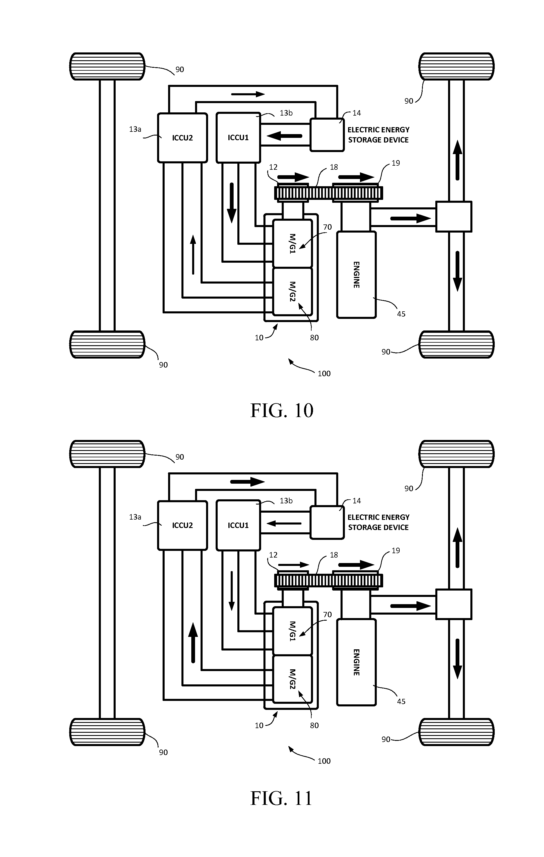
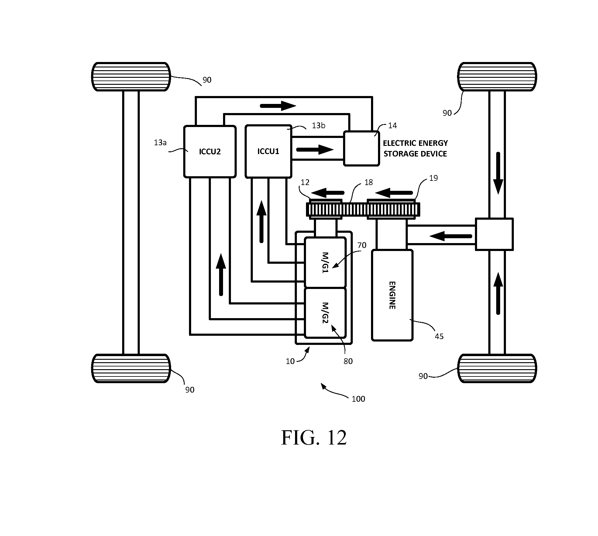
State III
Cruising Speed Mode
State IV
Deceleration and Braking Modes