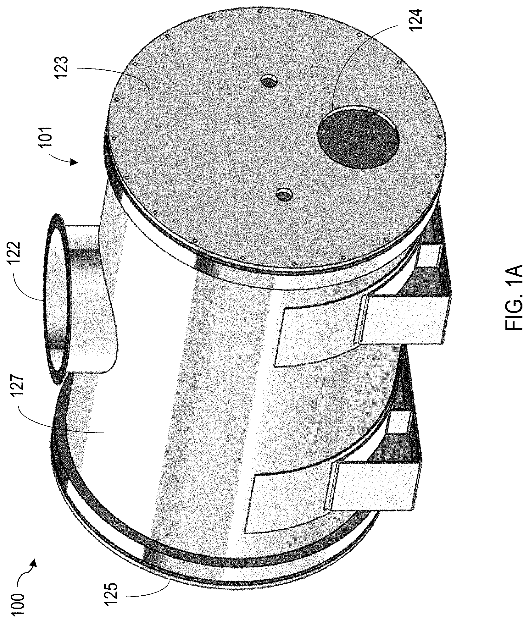
Process vessel for forming fuel compositions and related systems and methods
This application claims the benefit of U.S. Patent Application No. 62/652,840, filed on Apr. 4, 2018, which is incorporated by reference herein in its entirety. This disclosure relates to a process vessel for producing solid compositions, as well as related systems and methods. In particular, a process vessel for producing solid fuel compositions from solid wastes are disclosed herein. It is desirable to manage solid wastes, such as municipal wastes from residential, institutional, and commercial sources, agricultural wastes, and other wastes such as sewage sludge. As landfills reach and exceed capacity worldwide, and as the solid waste industry and societies generally limit the use of landfills, methods of managing solid wastes have been developed to reduce the volume of solid waste introduced into landfills. Recycling of metals, plastics, and paper products, as well as composting organic matter are methods of reducing the overall volume of solid wastes going to landfills. Waste-to-energy processes have also been developed to convert the energy content of solid wastes into a more usable form, such as electrical power. This disclosure relates to a process vessel for producing compositions, such as solid fuel compositions, having a desired homogeneity, density and/or moisture content, as well as related systems and methods. In particular, some embodiments provided herein include a process vessel, a system, and a method for producing solid fuel compositions from solid wastes. For example, the process vessel provided herein can produce a desired composition (e.g., a solid fuel composition) from feedstock materials (e.g., solid wastes and other wastes). In one general aspect, this disclosure provides a process vessel including a first shell and a second shell disposed within the first shell. The second shell includes a first end, a second end, and a wall extending between the first end and the second end. The second shell defines a cavity and a longitudinal axis extending between the first end and the second end. A cross section of the second shell transverse to the longitudinal axis includes a first arcuate inner wall portion having a first radius of curvature. The cross section of the second shell transverse to the longitudinal axis includes a second arcuate inner wall portion having a second radius of curvature. The first radius of curvature is larger than the second radius of curvature. Certain aspects of the subject matter described in this disclosure can be implemented as a system including a composition and a process vessel configured for processing the composition. The process vessel includes an inlet opening, an outlet opening, a first shell, and a second shell disposed within the first shell. The second shell includes a first end, a second end, and a wall extending between the first end and the second end. The second shell defines a cavity to hold the composition during processing and a longitudinal axis extending between the first end and the second end. A cross section of the second shell transverse to the longitudinal axis includes a first arcuate inner wall portion having a first radius of curvature and a second arcuate inner wall portion having a second radius of curvature. The first radius of curvature is larger than the second radius of curvature. The process vessel is configured to form, from the composition, a solid fuel composition including an energy content of at least about 8,000 British thermal units per pound. Certain aspects of the subject matter described in this disclosure can be implemented as a method. A composition is heated within a process vessel. The process vessel includes a first shell and a second shell disposed within the first shell. The second shell includes a first end, a second end, a wall extending between the first end and the second end, and a heating jacket coupled to the wall. The heating jacket is configured to heat the wall. The second shell defines a cavity to hold the composition during processing. The second shell defines a longitudinal axis extending between the first end and the second end. A cross section of the second shell transverse to the longitudinal axis includes a first arcuate inner wall portion having a first radius of curvature and a second arcuate inner wall portion having a second radius of curvature. The first radius of curvature is larger than the second radius of curvature. The composition is mixed with first and second mixers disposed in the cavity of the second shell. As used herein, “mix” generally refers to agitate, combine, or blend. The composition is extruded with an extruder element disposed in the cavity of the second shell. As used herein, “extruded” generally refers to densified or shaped, and “extruder element” generally refers to a device suitable for densifying or shaping a solid composition. A solid fuel composition is formed from the composition. The solid fuel composition includes an energy content of at least about 8,000 British thermal units per pound. The aspects provided above, and other aspects, can include one or more of the following features. An annular enclosure can be defined between the first shell and the second shell. The process vessel can include one or more support structures disposed within the annular enclosure. At least a portion of the support structure can extend transverse to the longitudinal axis and can extend circumferentially about a portion of an exterior surface of the second shell. The process vessel can include a heating jacket coupled to the wall of the second shell. The heating jacket can be disposed along an inner surface of the wall of the second shell. The heating jacket can be disposed along an exterior surface of the wall of the second shell. The process vessel can include an insulating material disposed within the annular enclosure. The process vessel can include a pump operatively coupled to the first and second shells, and the pump can be configured to reduce a pressure within the cavity, the annular enclosure, or both. The process vessel can be configured so that, during use of the pump, the cavity has a first pressure, and the annular enclosure has a second pressure. The first and second pressures can be within a 10% deviation. The cavity can have a first pressure, and the annular enclosure can have a second pressure, where a pressure differential between the first and second pressures is no greater than 5 pounds per square inch. The first shell can include a first outer end, a second outer end, and first shell wall defining a cylindrical shape that extends between the first outer end and the second outer end. The cross section of the second shell transverse to the longitudinal axis can include a third arcuate inner wall portion and a fourth arcuate inner wall portion. The second arcuate inner wall portion can extend between the third arcuate inner wall portion and the fourth arcuate inner wall portion. The third arcuate inner wall portion can have a third radius of curvature, and the fourth arcuate inner wall portion can have a fourth radius of curvature that is identical to the third radius of curvature The third arcuate inner wall portion and the fourth arcuate inner wall portion can each have a radius of curvature that is larger than the second radius of curvature of the second arcuate inner wall portion. The second arcuate inner wall portion can form a channel between curved surfaces formed by the third arcuate inner wall portion and the fourth arcuate inner wall portion. The process vessel can include an extruder element disposed in the cavity of the second shell, a first mixer disposed in the cavity of the second shell, and a second mixer disposed in the cavity of the second shell. The longitudinal axis can be a first longitudinal axis. The extruder element can define a second longitudinal axis. The first mixer can define a third longitudinal axis. The second mixer can define a fourth longitudinal axis. The extruder element can be disposed adjacent to the second arcuate inner wall portion. The first mixer can be disposed adjacent to the third arcuate inner wall portion. The second mixer can be disposed adjacent to the fourth arcuate inner wall portion. The extruder element can include an extrusion screw. The first mixer and the second mixer can each include a rotary mixing blade. The extruder element can be disposed within the channel. The extruder element can be spaced apart from each of the first mixer and the second mixer by a first gap, and the first mixer and the second mixer can be spaced apart from each other by a second gap. The second gap can be larger than the first gap. The second, third, and fourth longitudinal axes can be offset from the first longitudinal axis. The first longitudinal axis can be separated from the third longitudinal axis and the fourth longitudinal axis by a first distance and a second distance, respectively, where a difference between the first and second distances is no more than 5% of the first or second distance. The first longitudinal axis can be separated from the third longitudinal axis and the fourth longitudinal axis by a first distance and a second distance, respectively, where a difference between the first and second distances is no more than 0.5 meters (m). The first longitudinal axis can be parallel to the second longitudinal axis, the third longitudinal axis, the fourth longitudinal axis, or combinations of these. The second longitudinal axis can be separated from the third longitudinal axis and the fourth longitudinal axis by a third distance and a fourth distance, respectively, where a difference between the third and fourth distances is no more than 5% of the first or second distance. The second longitudinal axis can be separated from the third longitudinal axis and the fourth longitudinal axis by a third distance and a fourth distance, respectively, where a difference between the first and second distances is no more than 0.5 meters (m). The second, third, and fourth longitudinal axes can form a triangular geometry in the cross section of the second shell. The first, second, third, and fourth longitudinal axes can form a quadrilateral geometry in the cross section of the second shell. The second arcuate inner wall portion can define a central angle with respect to the extruder element. The central angle can extend from about 180 degrees)(° to about 300°. The third arcuate inner wall portion and the fourth arcuate inner wall portion can each define an arc length having an angle that extends from about 10 degrees)(° to about 60°. This, and other aspects, can include one or more of the following features. An annular enclosure can be defined between the first shell and the second shell. The system can include a heating jacket coupled to the wall of the second shell. The heating jacket can be configured to heat the wall of the second shell. The system can include an insulating material disposed within the annular enclosure. The system can include a pump system operatively coupled to the first and second shells, and the pump system can be configured to reduce the pressure or generate a vacuum within the cavity, the annular enclosure, or both. The pump system can be configured to set the cavity at a first pressure and set the annular enclosure at a second pressure, where the first and second pressures are equal. The pump system can be configured to set the cavity at a first pressure and set the annular enclosure to a second pressure, where a pressure differential between the first and second pressures is no greater than 5 pounds per square inch. The cross section of the second shell transverse to the longitudinal axis can include a third arcuate inner wall portion and a fourth arcuate inner wall portion. The process vessel can include an extruder element disposed in the cavity of the second shell, a first mixer disposed in the cavity of the second shell, and a second mixer disposed in the cavity of the second shell. The extruder element can be disposed adjacent to the second arcuate inner wall portion. The first mixer can be disposed adjacent to the third arcuate inner wall portion. The second mixer can be disposed adjacent to the fourth arcuate inner wall portion. The second arcuate inner wall portion can form a channel. The extruder element can be disposed within the channel. The first mixer can be configured to rotate the composition in a first direction, and the second mixer can be configured to rotate the composition in a second direction opposite the first direction. The extruder element can be configured to circulate the composition in the cavity or transport the solid fuel composition out of the process vessel through the outlet opening. The extruder element can be configured to, when the extruder element is rotating in a first direction, transport the solid fuel composition out of the process vessel through the outlet opening. The extruder element can be configured to, when the extruder element is rotating in a second direction, circulate the composition in the cavity. The subject matter described in this disclosure can be implemented in particular embodiments, so as to realize one or more of the following advantages. For example, in various embodiments, the process vessel provided herein can be used to transform a feedstock material(s) into a more useful composition by modifying, reducing, and/or eliminating one or more characteristics and/or elements of the feedstock material. For example, in some embodiments, the process vessel provided herein can form a desired composition (e.g., a solid fuel composition) from a feedstock (e.g., solid waste) that reduces or eliminates odors, bacteria, and other undesirable properties of the feedstock. In some embodiments, the process vessel described herein transforms a feedstock material (e.g., solid waste) having a variable composition (e.g., a mixture of different types of solid waste) into a composition (e.g., a solid fuel composition) that is a relatively consistent (e.g., homogeneous), more compact (e.g., having a high density), and/or has a low moisture content (e.g., dry, <2 wt. % water). In some embodiments, the process vessel provided herein can provide a solid fuel composition in the form of a homogenized, dry, dense, and energy-rich fuel primed for subsequent processing (e.g., pyrolysis or gasification). For example, the process vessel provided herein can produce a desired composition (e.g., a solid fuel composition) that provides efficient operation for subsequent processing (e.g., feedstock for a pyrolysis or gasification chamber as part of a waste-to-energy process) without additional capital investment in advanced machinery. The process vessel provided herein can produce the desired composition in a compact form having a density of at least 20 pounds per cubic foot (lb/ft3). In some embodiments, the process vessel provided herein produce the desired composition in a compact form having a density in a range from 20 lb/ft3to 80 lb/ft3, from 30 lb/ft3to 70 lb/ft3, from 40 lb/ft3to 60 lb/ft3, or from 42 lb/ft3to 57 lb/ft3. The process vessel provided herein can produce the desired composition having a moisture content of no more than 45 weight percent (wt %). In some embodiments, the process vessel provided herein produces the desired composition having a moisture content in a range from 1 wt % to 45 wt %, from 1 wt % to 15 wt %, from 1 wt % to 20 wt %, from 1 wt % to 30 wt %, from 1 wt % to 40 wt %, from 10 wt % to 40 wt %, or from 20 wt % to 30 wt %. In some embodiments, the process vessel provided herein provides a suitable design for heating, mixing, drying, and/or extruding the feedstock materials. For example, certain embodiments of the process vessel provided herein define a volume suitable for mixing and heating a composition (e.g., solid waste) such that air voids within the final composition (e.g., solid fuel composition) is reduced and/or to provide uniform dispersion of components in the final composition. In some embodiments, the process vessel includes at least two mixers (e.g., mixing blades) configured to actuate in a counter-rotation direction with respect to one another to improve circulation and mixing of the composition (e.g., solid waste) during processing. The configuration of the process vessel and manner in which the components move with respect to one another can improve moisture removal from the composition (e.g., solid waste). For example, the at least two mixers can circulate the composition (e.g., solid waste), such that moisture does not get entrapped or entrained within the composition. In some embodiments, the process vessel provided herein includes a pump for reducing pressure and/or removing moisture from the materials during processing of the composition (e.g., solid waste) at lower temperatures, which can reduce processing time, heat, and energy required for producing the desired final composition (e.g., solid fuel composition). The process vessel provided herein includes inner and outer shells. The inner and outer shell configuration can reduce inner structural reinforcement, which may otherwise be necessary due to vacuum operation within the process vessel. The inner and outer shell configuration can also increase heat transfer surface area, thereby increasing the overall heating efficiency of the process. The inner and outer shell configuration also enables the overall system to be rated for full vacuum operation. Vacuum operation also allows for higher operating temperatures to be achieved within the process vessel without the risk of combustion occurring within the process vessel. Breakdown of organic matter can be improved in vacuum operation within the process vessel provided herein. In some embodiments, the disclosure provides a size-efficient process vessel that can produce a densified, dry (e.g., <2 wt. % water) composition. The details of one or more embodiments of the subject matter of this disclosure are set forth in the accompanying drawings and the description. Other features, aspects, and advantages of the subject matter will become apparent from the description, the drawings, and the claims. This disclosure describes a process vessel for producing compositions, such as solid fuel compositions, as well as related systems and methods. In particular, the process vessel provided herein can produce a desired composition (e.g., a solid fuel composition) from feedstock materials (e.g., solid wastes and other wastes). For example, various embodiments of a process vessel (or a system) and a method for producing solid fuel compositions from a solid waste mixture are disclosed herein. In various embodiments, the process vessel provided herein is configured to process feedstock material that includes waste (e.g., solid waste). As used herein, “waste” refers to carbon-containing combustible material discarded after its primary use, and “solid waste” is any garbage, refuse, or sludge. In some embodiments, the process vessel provided herein is not limited to producing solid fuel compositions. For example, the process vessel (or a system) and method relating thereto provided herein may be used to produce other types of compositions from feedstock materials (e.g., a mixture of materials). In some embodiments, the process vessel provided herein can produce a desired composition (e.g., a uniformly mixed or blended solid composition) from feedstock materials (e.g., a mixture of different materials). In some embodiments, the process vessel provided herein can produce the desired composition having a moisture content less than the moisture content of the feedstock materials. For example, the process vessel provided herein can produce the desired composition having a moisture content of no more than 45 weight percent (wt %). In some embodiments, the process vessel provided herein can produce the desired composition in a compact form having a density higher than the density of the feedstock materials. For example, the process vessel provided herein can produce the desired composition in a compact form having a density of at least 20 pounds per cubic feet (lb/ft). The absolute and relative size of the outer shell can be varied as desired. For example, in some embodiments, the length of the outer shell 101 may range from about 5 feet to about 20 feet. In some embodiments, the height and width of the outer shell 101 may each range from about 5 feet to about 10 feet. In some embodiments, the outer shell 101 can have a length of about 9 feet, a width of about 6 feet, and a height of about 6 feet. In some embodiments, the length-to-width ratio of the outer shell is from about 0.5 to about 4.0, e.g., from about 0.75 to about 3.0, from about 1.0 to about 2.5, or from about 1.5 to about 2.0. In some embodiments, the length-to-height ratio of the outer shell is from about 0.5 to about 4.0, e.g., from about 0.75 to about 3.0, from about 1.0 to about 2.5, or from about 1.5 to about 2.0. In some embodiments, the width-to-height ratio of the outer shell is from about 0.5 to about 2, e.g., from about 0.75 to about 1.75, or from about 1.0 to about 1.5. The inner shell 102 of the process vessel 100 is disposed within the outer shell 101. The inner shell 102 includes a first end 103, a second end 105, and a wall 107 extending between the first end 103 and the second end 105. The inner shell 102 defines a cavity 111 and a longitudinal axis 180 The outer shell 101 can include one or more metals (including alloys thereof), ceramics, polymers, composites, or combinations thereof. Examples of suitable materials for constructing the outer shell 101 include, but are not limited to, titanium, stainless steel, carbon steel, and combinations or alloys thereof. In some embodiments, the material (e.g., a metal) includes an internal wetted surface, such as a metallic coating or metallic cladding suitable for providing oxidation resistance. The inner shell 102 can include one or more metals (including alloys thereof), ceramics, polymers, composites, or combinations thereof. Examples of suitable materials for constructing the inner shell 102 include, but are not limited to, titanium, 304 class stainless steel, 316 class stainless steel, appropriate chromium/nickel alloys, and other alloy variants resistant to oxidation and abrasion. The process vessel 100 can include a heating structure coupled to or forming an exterior surface of the inner shell 102 or coupled to or forms an interior surface of the inner shell 102. The heating structure may be in the form of a heating jacket. In some embodiments, a heating jacket 109 is coupled to or forms a surface of the wall 107 of the inner shell 102. In some embodiments, the heating jacket 109 is disposed along or forms an exterior surface of the wall 107 of the inner shell 102. In some embodiments, the heating jacket 109 is disposed along or forms an inner surface of the wall 107 of the inner shell 102. The heating jacket 109 can heat the wall 107 of the inner shell 102. Any suitable heater design may be selected as the heating jacket 109, such as an electrical heating jacket, an inductive heating jacket, or a convective heating jacket (for example, a heated oil jacket). The heating jacket 109 transfers heat into the cavity 111, and the solid waste mixture may be heated within the cavity 111 through conduction from the heating jacket 109 to a portion of the solid waste mixture in contact with the heating jacket 109 and through convection. In some embodiments, the heating structure (e.g., heating jacket) includes a second shell installed over a portion of a wall of the vessel that forms an annular space containing a heating (or cooling) medium. In some embodiments, an exemplary heating structure includes half-pipe coil jackets, dimple jackets, plate coils, and pillow plates. A heat transfer fluid can be circulated through the heating structure (e.g., heating jacket 109) as a heating medium. The heat transfer fluid flows through the heating structure to provide heat to the process vessel 100. A heater can be included to heat the heat transfer fluid, and a circulation pump can be included to circulate the reheated heat transfer fluid to the heating structure. The heat transfer fluid can be, for example, a heated oil. In some implementations, the heating structure includes a hollow shell with heated oil circulating within the hollow shell. In some implementations, the heating structure is one, continuous member. In some implementations, the heating structure is made up of multiple, discrete portions. In some embodiments, the heating structure can include multiple heating panels formed around and welded to the outer surface of the inner shell 102. The temperature of the heated oil may be increased by passing the oil through any suitable heat exchanger. In some embodiments, the process vessel 100 can include a plurality of heating structures. The outer shell 101 is configured to withstand an internal vacuum. An annular enclosure 150 is defined between the outer shell 101 and the inner shell 102. The process vessel 100 can include a pump (e.g., a vacuum pump) operatively coupled to the outer shell 101 and the inner shell 102. The pump can be used so that a difference between the pressure in the cavity 111 and the pressure in the annular enclosure 150 is no greater than 5 pounds per square inch (psi). In some embodiments, the pump can be used such that the pressure within the cavity 111 and the pressure within the annular enclosure 150 are equal. In some embodiments, the inner shell 102 does not experience a pressure differential because the pressure within the inner shell 102 (that is, the pressure within the cavity 111) and the pressure exterior to the inner shell 102 (that is, the pressure within the annular enclosure 150) are equal. Therefore, the inner shell 102 can have a thickness that is thinner in comparison to a shell that would need to be designed to withstand a pressure differential between an interior vacuum operation and the atmosphere. Additionally, the process vessel 100 can include an insulating material 108 disposed within the annular enclosure 150, so that heat losses to the surrounding environment (for example, through the outer shell 101 to the atmosphere) can be decreased. By surrounding the inner shell 102 with insulating material 108, the energy efficiency of the process vessel can be increased. Suitable insulating materials can withstand high temperature operation, for example, at least up to the maximum temperature of the heating structure (e.g., heating jacket 109). In some embodiments, the insulating material 108 can be hydrophobic to reduce or prevent moisture buildup in the annular cavity. In some embodiments, the insulating material 108 can be chemically inert to reduce or prevent deterioration of the insulating material over time. The insulating material 108 can optionally have a high density. Examples of suitable insulating materials include, but are not limited to, cellular gas and ceramic fiber. In some embodiments, the insulating material 108 is coupled to the inner shell 102. In some embodiments, the insulating material 108 covers at least a portion of the heating jacket 109. In some embodiments, the insulating material 108 is coupled to the heating jacket 109. The insulating material 108 can be coupled to the outer shell 101 (for example, an inner surface of the outer shell 101). The insulating material 108 can be coupled to the inner shell 102 (for example, an inner surface of the inner shell 102, an outer surface of the inner shell 102, or both). The insulating material 108 can be coupled to one or multiple support structures 152. The inner shell 102 is maintained in position within the outer shell 101 by a support structure 152 (best shown in The extruder element 115 is a compression element configured to compress the solid waste mixture toward the opening, thereby forcing the solid waste mixture through the opening. For example, the compression element can include a mixer blade, a screw conveyer, a piston, a compression pump, or the like. The extruder element 115 circulates material (for example, a composition such as a solid waste mixture) within the cavity 111 of the inner shell 102 or transport material (such as a solid fuel composition) out of the process vessel 100 through the outlet 124. For example, when the extruder element 115 is rotating in a first direction, the extruder element 115 can transport a solid fuel composition out of the process vessel 100 through the outlet 124. When rotating in a second direction (for example, in a direction opposite the first direction), the extruder element 115 can circulate a composition in the cavity 111. The extruder element 115 can be an extrusion screw. The outlet 124 can optionally be heated to facilitate extrusion of the solid waste mixture out of the process vessel 100. For example, the outlet 124 can be operatively connected to an extrusion heater, such as an electrical heater, an inductive heater, or a convective heater. The first mixer 113 Still referring to The “outer diameter” of a rotating component (for example, the first mixer 113 In some embodiments, the cavity 111 is subdivided into separate drying and mixing chambers. The drying chamber and the mixing chamber can independently be surrounded by the heating jacket 109 to heat contents of either chamber. In some embodiments, a resealing door can be included in between the separate chambers, and the resealing door can be opened or otherwise moved to allow transfer of material between the drying chamber and the mixing chamber. In some embodiments, a partition can be included in between the separate chambers, and the partition can be moved to allow transfer of material between the drying chamber and the mixing chamber. The process vessel 100 can include an exhaust port on the first shell wall 127 to provide an operative coupling to the pump (e.g., vacuum pump). In some embodiments, the pump is connected to the exhaust port with a hose (e.g., a vacuum hose), which may be reinforced to prevent collapse during use. The hose may also be heat-resistant or include insulation to allow safe operation at temperatures up to the maximum temperature to which the solid waste mixture is heated within the process vessel 100. The pump can be selected to maintain a sufficiently low pressure as described in this disclosure, within the cavity 111. The pump may be placed on a stand or a raised platform to prevent the pump from exposure to liquid water during incidental flooding. Any pump design may be included without limitation. For example, the pump can include a rotary vane pump, a diaphragm pump, or a liquid ring pump. The pump can optionally include one or more pumps connected in series. In some embodiments, the pump includes a condenser operatively connected to the process vessel 100. The condenser cools water vapor and other vaporized compounds drawn from the cavity 111 by the pump to produce wastewater. The wastewater can be transferred to a wastewater reservoir, such as another vessel or a tank. A water treatment device operatively coupled to the wastewater reservoir can be configured to remove compounds from the condensed wastewater to produce treated wastewater. The water treatment device can include membrane filters, ozone chambers, activated carbon filters, or combinations thereof. In some embodiments, the pump includes a gas scrubbing device, to which any air remaining in the condenser after the vaporized compounds have been condensed can pass through the pump and be exhausted. The gas exiting the pump (in other words, the exhaust) may include air, methane, chlorine, chlorinated organic compounds, and volatile organic compounds. The gas scrubbing device can include an adsorbent bed to separate methane and other combustible gases from the exhaust. The methane and other combustible gases captured by the adsorbent bed can be used as fuel, stored for later use, or be sold. The gas scrubbing device can include a gas filter, such as an activated carbon filter or a membrane filter. The gas remaining after treatment by the gas scrubbing device may be exhausted to the atmosphere. The process vessel 100 includes an air source operatively coupled to the process vessel 100 through an air inlet port. The air source can introduce sweep air into the cavity 111 of the inner shell 102 to facilitate movement of vaporized compounds out of the cavity 111 and into the pump. The air source can provide air at a flow rate selected to maintain the desired pressure (e.g., vacuum) within the cavity 111 while the pump is operating. The air source may be any known air source, such as a compressed air tank, an air compressor, an air pump, or a fan drawing in atmospheric air. In some embodiments, the air source may supply an oxygen-free and non-reactive gas, such as nitrogen or a noble gas. In some embodiments, the process vessel 100 includes a cutter configured to cut the solid waste mixture into discrete pieces, as the solid waste mixture is extruded out of the outer shell 101. For example, the cutter can be a laser cutter, a saw, or a water jet cutter. In some embodiments, the solid waste mixture is slightly cooled in order to harden the solid waste mixture prior to cutting. As an example, the solid waste mixture can be cut into discrete pieces that are less than about 2 feet in length. The system 400 provided herein can be configured to process a composition 450 A variety of sources of solid waste can be used. The solid waste mixture may be derived from non-hazardous waste sources including, but not limited to, municipal waste, agricultural waste, commercial waste, household waste, mining waste, discarded secondary materials, industrial solid waste, and sewage sludge from a wastewater treatment plant, a water supply treatment plant, or an air pollution control facility. “Municipal waste” or “municipal solid waste” (MSW), as used here, generally refer to any household waste, commercial solid waste, or industrial solid waste. Non-limiting examples of wastes that can be included in the solid waste mixture include biodegradable waste, such as food and kitchen waste; green wastes, such as lawn or hedge trimmings; paper; mixed plastics; solid food waste; solid agricultural waste; sewage sludge; and automotive shredder residue. “Household waste” or “residential waste” generally refers to any solid waste (including garbage, trash, and sanitary waste in septic tanks) derived from households (including single and multiple residences, hotels and motels, bunkhouses, ranger stations, crew quarters, campgrounds, picnic grounds, and day-use recreation areas). “Commercial solid waste” generally refers to all types of solid waste generated by stores, offices, restaurants, warehouses, and other non-manufacturing activities. “Industrial solid waste” generally refers to non-hazardous solid waste generated by manufacturing or industrial processes. Examples of industrial solid waste include, but are not limited to, waste resulting from manufacturing processes, such as electric power generation; fertilizer and agricultural chemicals; food and related products and by-products; leather and leather products; organic chemicals; plastics and resins manufacturing; pulp and paper products; rubber and miscellaneous plastic products; textile manufacturing; transportation equipment; and water treatment. The composition 450 The composition 450 Still referring to The process vessel 499 includes an annular enclosure 450 defined between the outer shell 401 and the inner shell 402. The process vessel 499 can include a heating structure (e.g., the heating jacket 409 coupled to the wall of the inner shell 402), and the heating structure can heat the wall of the inner shell 402. The process vessel 499 can include an insulating material 408 disposed within the annular enclosure 450. The process vessel 499 can include a pump system operatively coupled to the outer shell 401 and the inner shell 402. The pump system can reduce the pressure or generate a vacuum within the cavity 411, the annular enclosure 450, or both. The pump system can set the cavity 411 at a first pressure and the annular enclosure 450 at a second pressure. The first pressure of the cavity 411 and the second pressure of the annular enclosure 450 can be equal. In some embodiments, a pressure differential between the first pressure of the cavity 411 and the second pressure of the annular enclosure 450 is no greater than 5 psi. The cross section of the inner shell 402 transverse to the longitudinal axis 480 The first mixer 413 The solid fuel composition 450 In some embodiments, the solid fuel composition 450 The solid fuel composition 450 The solid fuel composition 450 The solid fuel composition 450 The solid fuel composition 450 The solid fuel composition 450 The solid fuel composition 450 The solid fuel composition 450 The solid fuel composition 450 A vacuum can be pulled within the process vessel 499, such that a pressure within the cavity 411 is below atmospheric pressure. In some embodiments, the pressure within the process vessel 499 (and within the cavity 411) is maintained at about 50 torr. The vacuum not only reduces the boiling temperature of water and other compounds in the composition 450 At 504, the composition 450 The heating structure (e.g., heating jacket 409) can provide heat to the composition 450 The heating jacket 409 can be maintained at a temperature corresponding to a maximum temperature of the composition 450 The composition 450 At 506, the composition 450 At 508, a solid composition (such as the solid fuel composition 450 The method 500 of forming a solid composition can be completed as a batch process, in which, for example, the solid waste mixture 450 The following description applies to a non-limiting exemplary process vessel. The outer shell 401 of the process vessel 499 had an inside diameter in a range between 60 inches and 90 inches. The outer shell 401 had a length in a range between 90 inches and 126 inches. Each of the at least two mixing blades (the first mixer 413 The total inner volume of the process vessel 499 (that is, the volume within the outer shell 401) was in a range of 210 cubic feet (ft3) and 230 ft3(5,947 liters (L) and 6,513 L). The working volume of the process vessel 499 (that is, the volume within which the solid waste mixture 450 The total area of the cross-sectional shape of the inner shell 402 was in a range between 20 square feet (ft2) and 30 ft2. The heating jacket 409 lined the outer surface of the inner shell 402 and defined the heated surface area. The heated surface area was in a range between 180 ft2and 220 ft2. The ratio between the heated surface area and the total surface area of the process vessel 499 was in a range between 0.5 and 0.9. The heating jacket 409 was supplied with hot oil (Duratherm 630™) at a flow rate in a range between 130 gallons per minute (gpm) and 170 gpm and a temperature in a range between 600° F. and 650° F. The process of forming the solid fuel composition 450 Although this disclosure contains many specific embodiment details, these should not be construed as limitations on the scope of the subject matter or on the scope of what may be claimed, but rather as descriptions of features that may be specific to particular embodiments. Certain features that are described in this disclosure in the context of separate embodiments can also be implemented, in combination, in a single embodiment. Conversely, various features that are described in the context of a single embodiment can also be implemented in multiple embodiments, separately, or in any suitable sub-combination. Moreover, although previously described features may be described as acting in certain combinations and even initially claimed as such, one or more features from a claimed combination can, in some cases, be excised from the combination, and the claimed combination may be directed to a sub-combination or variation of a sub-combination. Particular embodiments of the subject matter have been described. Other embodiments, alterations, and permutations of the described embodiments are within the scope of the following claims as will be apparent to those skilled in the art. While operations are depicted in the drawings or claims in a particular order, this should not be understood as requiring that such operations be performed in the particular order shown or in sequential order, or that all illustrated operations be performed (some operations may be considered optional), to achieve desirable results. Accordingly, the previously described example embodiments do not define or constrain this disclosure. Other changes, substitutions, and alterations are also possible without departing from the spirit and scope of this disclosure. This disclosure relates to a processing that includes a first shell and a second shell disposed within the first shell. The second shell includes a first end, a second end, and a wall extending between the first end and the second end. The second shell also defines a cavity and a longitudinal axis extending between the first end and the second end. A cross section of the second shell transverse to the longitudinal axis includes a first arcuate inner wall portion having a first radius of curvature and a second arcuate inner wall portion having a second radius of curvature. The first radius of curvature is larger than the second radius of curvature. 1. A vessel comprising:
a first shell; and a second shell disposed within the first shell, the second shell comprising a first end, a second end, and a wall extending between the first end and the second end, the second shell defining a cavity and a longitudinal axis extending between the first end and the second end, a cross section of the second shell transverse to the longitudinal axis including: a first arcuate inner wall portion having a first radius of curvature; and a second arcuate inner wall portion having a second radius of curvature; wherein the first radius of curvature is larger than the second radius of curvature; and wherein the first shell comprises a first outer end, a second outer end, and a first shell wall defining a cylindrical shape that extends between the first outer end and the second outer end. 2. The vessel of 3. The vessel of 4. The vessel of 5. The vessel of 6. The vessel of 7. The vessel of 8. The vessel of 9. The vessel of 10. The vessel of 11. The vessel of 12. The vessel of 13. The vessel of 14. The vessel of an extruder element disposed in the cavity of the second shell; a first mixer disposed in the cavity of the second shell; and a second mixer disposed in the cavity of the second shell; wherein the longitudinal axis is a first longitudinal axis, the extruder element defines a second longitudinal axis, the first mixer defines a third longitudinal axis, and the second mixer defines a fourth longitudinal axis. 15. The vessel of 16. The vessel of 17. The vessel of 18. A system comprising:
a composition; and a process vessel configured for processing the composition, the process vessel comprising: an inlet opening; an outlet opening; a first shell; and a second shell disposed within the first shell, the second shell comprising a first end, a second end, and a wall extending between the first end and the second end, the second shell defining a cavity to hold the composition during processing and a longitudinal axis extending between the first end and the second end, a cross section of the second shell transverse to the longitudinal axis including: a first arcuate inner wall portion having a first radius of curvature, and a second arcuate inner wall portion having a second radius of curvature, wherein the first radius of curvature is larger than the second radius of curvature, and wherein the cross section of the second shell transverse to the longitudinal axis comprises a third arcuate inner wall portion and a fourth arcuate inner wall portion; wherein the process vessel is configured to form, from the composition, a solid fuel composition comprising an energy content of at least about 8,000 British thermal units per pound. 19. A method comprising:
heating a composition within a process vessel, the process vessel comprising: a first shell; and a second shell disposed within the first shell, the second shell comprising: a first end; a second end; a wall extending between the first end and the second end; and a heating structure coupled to the wall, the heating structure configured to heat the wall, wherein the second shell defines a cavity to hold the composition during processing and a longitudinal axis extending between the first end and the second end, a cross section of the second shell transverse to the longitudinal axis comprising a first arcuate inner wall portion having a first radius of curvature and a second arcuate inner wall portion having a second radius of curvature, wherein the first radius of curvature is larger than the second radius of curvatures and wherein the first shell comprises a first outer end, a second outer end, and a first shell wall defining a cylindrical shape that extends between the first outer end and the second outer end;
mixing the composition with first and second mixers disposed in the cavity of the second shell; extruding the composition with an extruder element disposed in the cavity of the second shell; and forming, from the composition, a solid fuel composition comprising an energy content of at least about 8,000 British thermal units per pound.CROSS-REFERENCE TO RELATED APPLICATION
TECHNICAL FIELD
BACKGROUND
SUMMARY
BRIEF DESCRIPTION OF DRAWINGS
DETAILED DESCRIPTION
EXAMPLE
Other Embodiments


CPC - классификация
BB0B01B01FB01F1B01F15B01F15/B01F15/0B01F15/02B01F15/028B01F15/0289B01F15/06B01F15/065B01F2B01F20B01F201B01F2015B01F2015/B01F2015/0B01F2015/06B01F2015/062B01F203B01F2035B01F2035/B01F2035/9B01F2035/99B01F27B01F27/B01F27/0B01F27/07B01F27/072B01F27/0727B01F27/7B01F27/70B01F27/708B01F3B01F35B01F35/B01F35/7B01F35/75B01F35/754B01F35/7545B01F35/75455B01F35/754551B01F35/9B01F35/92B01F7B01F7/B01F7/0B01F7/00B01F7/001B01F7/0017B01F7/00175B01F7/04B01F7/046B01JB01J1B01J19B01J19/B01J19/0B01J19/00B01J19/006B01J19/0066B01J19/2B01J19/20B01J2B01J22B01J221B01J2219B01J2219/B01J2219/0B01J2219/00B01J2219/000B01J2219/0008B01J2219/00085B01J2219/1B01J2219/18B01J2219/182B01J2219/19B01J2219/194B01J2219/1943B01J2219/3B01J2219/31B01J2219/318B01J2219/3188B01J8B01J8/B01J8/1B01J8/10CC1C10C10BC10B7C10B7/C10B7/1C10B7/10C10JC10J3C10J3/C10J3/0C10J3/00C10J3/005C10J3/007C10J3/7C10J3/74C10LC10L2C10L22C10L229C10L2290C10L2290/C10L2290/0C10L2290/06C10L2290/2C10L2290/24C10L2290/5C10L2290/50C10L2290/56C10L2290/565C10L5C10L5/C10L5/0C10L5/06C10L5/4C10L5/44C10L5/445C10L5/46C10L5/48C10L9C10L9/C10L9/0C10L9/08C10L9/083YY0Y02Y02EY02E5Y02E50Y02E50/Y02E50/1Y02E50/10Y02E50/3Y02E50/30IPC - классификация
BB0B01B01JB01J1B01J19B01J19/B01J19/0B01J19/00B01J19/2B01J19/20B01J8B01J8/B01J8/1B01J8/10CC1C10C10BC10B7C10B7/C10B7/1C10B7/10C10JC10J3C10J3/C10J3/0C10J3/00C10J3/7C10J3/74C10LC10L5C10L5/C10L5/0C10L5/06C10L5/4C10L5/44C10L5/46C10L5/48C10L9C10L9/C10L9/0C10L9/08Цитирование НПИ
366/149366/185
366/299
508/539
Canova, Joseph H., Testing and Evaluating the Combustion Characteristics of Waste Fuels, 1992, 120 pages.
Even et al., “Evaluation of the Ames Solid Waste Recovery System”, Part I, Summary of Environmental Emissions: Equipment, Facilities, and Economic Evaluations, EPA-600/2-77-205, Nov. 1977, 215 pages.
Fritsky et al., “Methodology for Modeling the Devolatilization of Refuse-Derived Fuel from Thermogravimetric Analysis of Municipal Solid Waste Components”, J. Air & Waste Manage. Assoc. 44:9, 1994, 9 pages.
Garg et al., “Wastes as Co-Fuels: The Policy Framework for Solid Recovered Fuel (SRF) in Europe, with UK Implications”, Environ. Science & Tech. 41.14, 2007, 19 pages.
Gendebien et al., “Refuse Derived Fuel, Current Practice and Perspectives (B43040/2000/306517/MAR/E3)”, Final Report No. CO 5087-4, Jul. 2003, 229 pages.
International Search Report and Written Opinion in International Application No. PCT/US2019/025844, dated Jun. 28, 2019, 14 pages.
Kresta et al.—Hangbook of Industrial Mixing: Science and Practice—year 2004.
Olexsey, “Evaluation of the Performance of the Disc Screens Installed at the City of Ames, Iowa Resource Recovery Facility”, Proc. ASME National Solid Waste Processing Conf., Washington, DC, 1980, 11 pages.
Raghunathan, K., et al., “Prevention of PCDD/PCDF Formation by Coal Co-Firing”, U.S. Environmental Protection Agency, Air Pollution Prevention and Control Division, 1998, 15 pages.
Study of Existing RDF-Cofiring Experience, vol. 3: Phase II Final Report, ANL/CNSV-TM-134, vol. 3, Oct. 31, 1983, 180 pages.
Yu Jie et al., “Thermal degradation of PVC: A review”, Waste Management, vol. 48, Dec. 10, 2015, pp. 300-314.