Laminated assembly for active bioelectronic devices
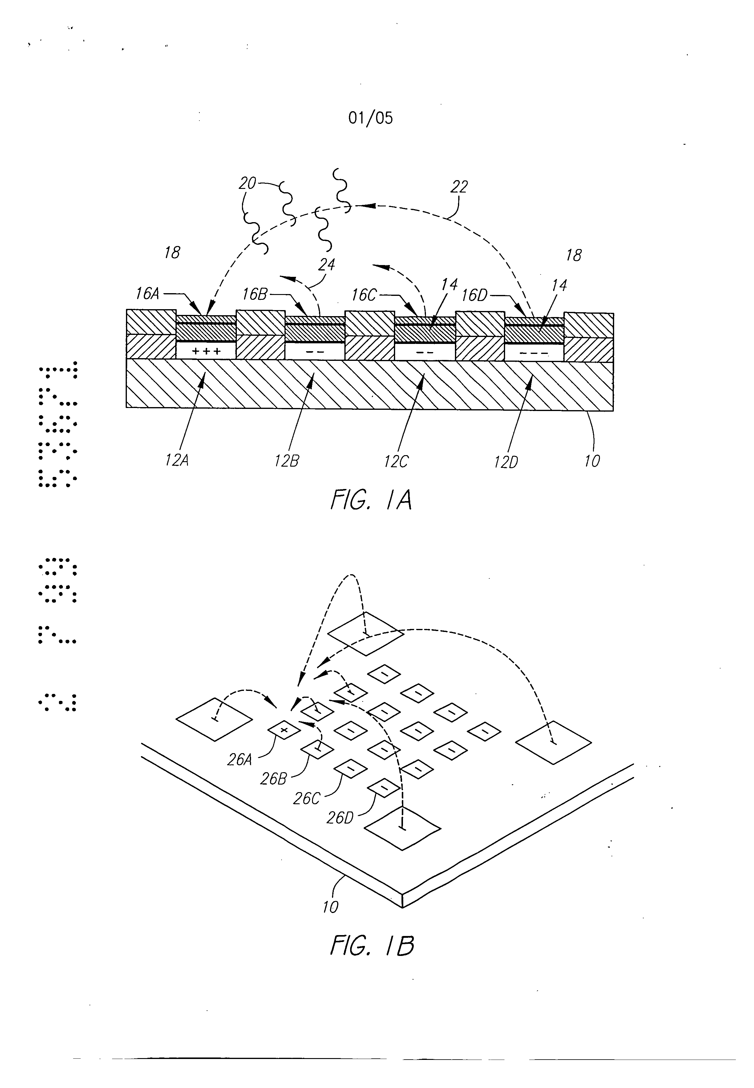
Molecular biology comprises a wide variety of techniques for the analysis of nucleic acid and protein. Many of these techniques and procedures form the basis of clinical diagnostic assays and tests These techniques include nucleic acid hybridisation analysis, restriction enzyme analysis, genetic sequence analysis, and the sepm-ation and pudficadon of nucleic acids and protdus (See, e.g., J. Sambmok, E. F. Ffitsch, and T. Maniacs, Molecular Cloninv A Laboratory Manual. 2 Ed., Cold spring Harbor Laboratory Press, Cold Spring Harbor, New York, 1989). Most of these techniques involve carrying out numerous operations (e.g., pipc iccnuifugations, electrophoreals)on a large number of samples. Th©y are often complex and time consuming, and genitally r luire a high degree of accuracy. Many a technique is limited in it application by a lark of sensitivity, specificity, or reproducibility. For example, these problems have limited many diagnostic applications ofnucieic acid fibrillation analysis. The complete process for carrying out a DNA hybridization analysis for a genetic or infectious disease is very involved. Broadly speaking, the complete process may be divided into a number of steps and substeps (see Figure 1). In the case of genetic disease diagnosis, the first step involves obtaining the sample (blood or tissue), Unending on the type of sample, various pre-trea nents would be carded out. The second step involves disrupting or lysing the cells, which then release the crude DNA material along with other cellular constituents. Generally, several substeps arc necessary to remove cell debris and to purify further the crude DNA. At this point several options exist for further processing and analysis. One option involves dcnat ing the purified sample DNA and'carrying out s direct hybridization analysis in one of many formats (dot blot, microbead, mlcroplate, etc.). A second option, called Southern blot hybridization, involves cleaving the DNA with restriction enzymes, separating the DNA fragments on an €lectmphoretic gel, blotting to a membrane filter, and then hybridizing the blot wi1 specific DNA probe sequences. This procedure effectively reduces the complexity of the genomic DNA sample, and thereby helps to improve the hybridization spu:ificity and sensitivity. Unforrtmately, this procedure is long and arduous. A third option is to carry out the polymerase chain reaction (PCR) or ogler amplification procedure. The PCR procedure amplifies (increases) the number of target DNA sequences relative to non-t rgct sequences. Amplification of target DNA helps to overcome problems related to complexity and sensitivity in genomic DNA analysis. All these procedures are time consuming, relatively complicated, and add significantly to the cost era diagnostic test. After these sample preparation and DNA processing steps, the actual hybridization reason is performed. Finally, detection and data analysis convert the hybridization event into an anal c.< l vault The st s of sample preparation and process have typically been perform separate and a,,'t fz m € other steps ofhybridizaS.ion detection and analysis. Indeed, the various substeps comprising sample preparation and DNA processing have often be performed as a discrete operation separate and apart from the other substops. Considering these substeps in more det&i[, samples have been obtained through any number of means, such as obtah ng of full blood. tissue, or other biological fluid samples. In the case ofbloock the sample is pro- ceased to remove red blood cells and retain the desired nucleate (white) cells. This process is usually carried out by density gradient centrifugation. Cell disruption or lysis is then carried out on th= nucleated cells to release DNA, preferably by the technique of sort/cation, freeze/thawing, or by addition of lysine rcage ts. Crude DNA is then separated from the cellular debris by a centrifugation step. Prior to hybridization, double-stranded DNA is denatured into single-sU'anded form. Denaturation of the doublc-stx nded DNA hu generally been performed by the techniques involving heating (>Tin), changing salt consentration, addition of base (NaOH), or denaturing reagents (urea, fotrnamide, etc.). Workers have suggested denaturing DNA into its single-stranded form in an electrochemical cell. The theory is to be that there is electron transfer to the DNA at the intm-face of an electrode, which effectively weakens the double.stranded structun: and results in separation of the strands. See, generally, Stanley, "DNA Denaturation by an Electric Potential", U.K. patent application 2,247,889 published March 18, 1992. Nucleic acid hybridization analysis generally involves the detection of a very small number of specific target nucleic acids (DNA or RNA) with an excess of probe DNA, among a relatively large amount of complex non-target nucleic acids. The substrate of DNA complexity reduction in sample preparation have been utilized to help detect low copy numbs (i.e. 10,000 to 100,000) of nucleic acid targels. DNA complexity is overcome to some degree by amplification of target nucleic acid sequences using polymerase chain reaction (PCR). (See, M.A. Innis et al, Pr.otocols A Guide to Methods an4Anplications, Academic Press, 1990). While amplification resuRs in an enormous number of target nucleic acid scquen s that improve the subseq 1 J t direct probe hybridization step, amplification involves lengthy and cumbersome procedure that typically must be performed on a stand alone basis relative to the other substrate. Substantially complicate! and relatively large equipment is vvquimd to perform the amplification step, The actual h)4 ridization traction currents the most important and central step in the whole process. The hybridization step involves placing the prepared DNA sample in €ontact with a specific -port=r probe, at a set of optimal ¢omiiSomJ for hybridization to occur to the target DNA sequmce. Hybridization may be performed in any one of a number of formats. For example, multiple sample nucleic acid hybridization analysis has been conducted on a variety of filter and solid support formats (See G. A. Beltz et al., in Methods in vmo Vol. 100, Part B, Ih Wu, L. Grossman" I Moldave, Eds,, Academic Press, New York, Chapter 19, pp. 266-308, 1985). One format, the so-called "dot blot" hybridization, involves the non-€ovalent attadunent of target DNAs to tilter, which are subsequently hybridized with a radioisotope labeled probe(s). "Dot blot" hybridization gained wide-spread use, and many versions were developed (see M. L. M. Anderson and B. D. Young, in Nucleic A id Hybridization - A Pra tical.A ma B. D, Haines and S..T. Higgins, Eds., IRL Press, Washington, D.C. Chapter 4, pp. 73-111, 1985). It has been developed for multiple analysis of genomic mutations (D. Nanibhushan and D. Rabin, in BPA0228075, July 8, 1987) and for the detection of overlapping clones and the construction of genomic maps (G. A. Evans, in US Patent Nttmb=r 5,219,726, June 15, 1993), New technique are being developed for carrying out multiple sample nucleic acid hybridization analysis on micro.formatted multiplex or matrix devices (e.g., DNA chips) (sec M. Barinaga, 253 Science, pp. 1489, 1991; W. Bains, Biotechnology, pp. 757-758, 1992). These methods usually attach specific DNA sequences to yery small specific areas of a solid support such as micro-wells of a DNA chip. These hybridization formats are micro-scale versions of the €onventional "dot blot" and "sandwich" hybridization systems. The micro-formatted hybridization can be used to carry out "sequerming by hybridization" (SBH) (see M. Barinaga, 253 Science, pp. 1489, 1991; W. Bans, I0 Biotechnology, pp. 757-788, 1992). SBH makes use of all possible n-nucleotide oligomers (n-mers) to identify n-mera in an unknown DNA sample, which are subsequently aligned by algorithm analysis to produce the DNA sequence 01, Drmanac and R. Czkvenjakov, Yugoslav Patent Applic.Ltion #570/S7, 1957; R. Drmanac et al., 4 C-=nomics, 114, 19$9; Strezoska et al., 88 Proc, Natl. Acad. Sci. USA 10089, 1992; and R. Drmanac and R. B. Cflcvenjakov, U.S. Patent #5,202,231, April 13, 1993). There are two formats for carrying out SBH. Th© first format involves creating an array of all possible n-mers on a support, which is then hybridized with the target sequence. The second format involves attaching the target sequence to a support, which is substantially probed with all possible n-mcrs. Both formats have the fundamental problems of direct probe hybridizations and additional difficulties related to multiplex hybridizations. Southern, United Kingdom Patent Application GB 8g I0400, 1988; E. M. Southern eta[., 13 Genomic 1008. 1992, proposed using [he first format to analyze or sequence DNA. Southern identified a known single point mutation using PCR amplified genomic DNA, Southern also described a method for synthesizing an array of oligonucleotides on a solid Dupont for SBH. However, Southern did not address how to achieve optimal strhlgency condition for each oligonucleotide on an array, Concurrently, Drmanac el al., 260 Science 1649-1652, 1993. used the second format to sequence several short (116 bp) DNA sequences. Target DNAs were aRached to mcmbnme supports ("dot blot" format). Each filter was sequentially hybridized with 272 labeled I 0-mer and l l-mer oligonuclcotides. A wide range of suingcncy condition was used to achieve specific hybridization for each n-met probe; washing times varied from 5 minutes to overflight and temperatures from 0°C to 160C, Most probes required 3 hours of washing t 16°C. The filters had to be exposed for 2 to 18 hours in order to detect hybridization signals. The overall false positive hybridization rate was 5% in spite of the simple targetsequences, the reduced set of oligomer probes, and the use ofthc most stringent conditions available. A variety of methods exist for detection and analysis of the hybridization rvents. Depending on the reporter group (fiuorophor enzyme, radioisotope, etc.) used to label the DNA probe, detection and analysis ere carried out fluorimetzicaliy, colorimetricaily, or by autoradiography. By observing and mess,zing emitted radiation, such as fluorescent radiation or particle =mission, information may be obtained about the hybridization events. Ew n when detection methods have very high inUinsic sensitivity, detection of hybridization events is different because of th© background presence ot non-apecifically bound materials. A number of other factors also reduce the sensitivity and selectivity of DNA hybridization assays. In conventional fluorimetric detection systems, an excitation energy of one wavelength is delivered to the region of interim and energy of a different wavel mgth is remitted and detected. Large scale systems, generally those having a region of interest of two milfimeters Or greater, have been manufazturod in which the quality of the overall system is not inherently limited by the size requhzmcnts of the optical elements or the ability to place them in optical proximity to the region of i-tm-esL However, with small geometries, such as those below 2 millimeters, and especially those on the order of 500 microns or less in size of the region of interest, the conventional approaches to fluorimeter design have proved inadequate. G eraIly, the excitation and emission optical elements must be placed close to the region of interest. Preferably, a focused spot size is relatively smaU, often r uirmg sophisticated optical designs. FtW cr, because it is usually desirable to maximize the detectable area, the size of the optical components required to achieve these goals in relation to their distance from the region of interest becomes important, and in many cases, compromises the performance obtained. Accordingly, a need exists for an improved fluorescent d tion system. . Attempts have been made to combine certain processing st s or substeps together. For example, various microrobotie systems have been proposed for preparing arrays of DNA probe on a support material. For example, Beano etal., in t 1992 San Dieao Conference: Gene Recog idon. Novemb:r, 1992, used a microrobotic system to deposit rrdcro-droplets containing specific DNA sequences into individual microfabricatcd sample wells on a glass substrate. Generally, the prior art processes have be extremely labor and time intensive. For example, the PCR amplification process is time consuming and adds cost to the diagnostic assay. Multiple steps requiring human interwution either during the process or between processes is suboptimal in that there is a possibility of contamination and operator error. Further, the use of multiple machines or complicated robotic systems for performing the individual processes is often prohibitive except for the largest laboratories, both in terms of the expense and physical space requirements. As is apparent from the preceding discussion, numerous attempts have been made to provide effective techniques to conduct multi-step, multiplex molecular biological reactions. However, for the reasons stated above, these techniques are "piece-meal" and limited. These various approaches are not easily combined to form a system which can carry out a complete DNA diagnostic assay. Despite the long-recognised need for such a system, no satisfactory solution has been proposed previously. Summary of the Invention According to a first aspect, the present invention consists in a device for performing active biological operations on a sample comprising: a first planar sample support including at least one sample through hole, the sample through hole being adapted to receive permeation material, a planar electrode adjacent to the first planar sample support, including an electrode through region, a second planar support including a vent through hole, wherein the planar electrode is in a laminated relationship between the first planar sample support and the second planar support and in that the sample through hole, electrode through hole and vent through hole are in overlapping arrangement. According to a second aspect, the present invention consists in a laminated device for performing active biological operations on a sample comprising: a first planar sample support including at least one sample through hole, the sample through hole having a first lateral dimension, the sample through hole being adapted to receive a sample support material, a planar electrode adjacent the first planar sample support material, including an electrode through region, a second planar support including a vent through hole, the vent through hole having a lateral dimension wherein the planar electrode is in laminated relationship between the first planar sample support and the second planar support and in that the sample through hole, electrode through hole and vent through hole are in overlapping arrangement, and in that the lateral dimension of the sample though hole is different from the lateral dimension vent through hole. According to a third aspect, the present invention consists in a multilayer device for pertbrming active biological operations on a sample, the device adapted to receive the sample on a sample surface of the device, comprising: a first planar sample support including at least a sample through hole, the sample through hole being adapted to receive a sample support material, the sample support material providing at least a portion of said sample surface, a first planar electrode adjacent the first planar sample support, including an electrode through region, the first planar electrode being at a first distance from the sample surface, a second planar electrode, including an electrode through region, the second planar electrode being at a distance from the sample surface which is greater than that of the first planar electrode, the electrode through region of the second planar electrode being laterally disposed from, and not overlapping with, the electrode through region of the first planar electrode and an intervening planar support layer serving to support the second planar electrode, said intervening planar support layer including a through hole, said electrode through region of the second planar electrode being adjacent said through hole of the intervening planar support layer. Methods of manufacture and apparatus adapted for advantageous use in active electronic devices utilised for biological diagnostics are disclosed. In the preferred embodiment, a multilayer, laminated device incudes at least a first planar sample support, the planar sample support including a through hole, a planar electrode adjacent the planar sample support, the electrode including a through region, and a second planar support including a vent through hole, the planar electrode being in a laminated relationship between the first planar sample support and the second planar support, further characterised in that the sample through hole, electrode through region and vent through hole overlap one another. In the preferred embodiment, the planar support members may be formed of a thin, sheet-like material, most preferably a polyimide sheet such as DuPont Kapton TM. The preferred thickness of the planar support is in the range from 1 to 5 mils. The planar sample support material is advantageously selected to have properties consistent with the goals and purposes of the active biological device, for example, exhibiting low binding properties for DNA, having low inherent fluorescence, being relatively inert in an acidic environment and being nonconducting. Stacked or laminated structures may be formed through the use of multiple sheets. In e preferred embodiment, one or more additional layers are disposed above the planm" sample support in a direct towards the surface which will receive the biological n,.,V al. Similarly, a multilayer or l in od atrucUm: may be formed beneath the second planar support, The additional laminated layers would typically include through holes, which preferably would be a/igned with the remaining through holes or regions. Multilayer or laminated structure may be advantageously formed in numerous confi n -afions. In one -mbodiment, dectrodes may be disposed at differing depths relative to the sample side of the laminated device such that diff :m offset distances betwe, en the electrode and the sample applied to the dice are achieved. In this way, the different offset distances pemfit optin ation of various functors, such as where complexity reduction and assaying are performed on the same device. Electrodes may be formcd at different levels such as through use of an intcrven.ing planar support disposed between a first electrode and a second electrode at different levels. In one aspect of this invention, the lateral dimension of the through hole of the first planar sample support is different than the lateral width of the vent through hole of the second planar support. In one embodiment, the latm-al dimensions of the vent through hole and are larger than the lateral dimensions ofthe sample through hole. Prefm'ably, a permeation layer is included in the sample through hole at at least a portion of the writ through hole. Relatiw advantages of this embodiment po[emially include the advantageous venting of gas from reactions at or near the planar electrode through a region separate fxom the hybridization reaction, and the ability of this structure to lock in a permeation lays" disposed in the sample through hole, electrode through region and at least a portion of the vent through hole. An altema6ve embodiment has a sample through hole with a lateral dimension which is greater than the lateral dimension of the vent through hole. The planar electrode includes at least a portion oriented to face outward through the sample through hole. In another aspect of this invention, fluidic devices may be formed on, within, or adjacent to the laminated structures. 1=or example, a pump, such as a magnetically driven microminiature pump may be included within the laminated su'ucture. Fluids may be pumped or mowd through the system in such a manna. In yet another aspect of this invention, chap-on flexible circuit technology may be employed to hybridize electronic circuitry in operative contact with the active biological device. Further, multiple level interconnections may be formed, such as through use of vias connecting between one or more layers. In the preferred embodiment, these vias may be exposed to external of the device through the second planar support, rather than through the uppermost planar sample support which adapted to receive biological materials. The laminated circuit structures and methods of this invention are advantageously utilised in forming active biological devices. A device having a combination of biological complexity reduction and diagnostic assay, as well as counter electrodes may be formed on a single device. In yet another aspect of this invention, a rnultilayer, laminated structure may be utilised to perform biological amplification processes, especially polymerase chain reaction (PCR). Optionally, one or more heaters may be integrated into or formed adjacent the laminated structure to aid in the amplification process. Accordingly, it is an object of this invention in preferred embodiments to provide an active biological device having reduced costs of manufacture yet consistent with achieving a small size microlocation. It is yet another object of this invention in preferred embodiments to provide a device having a high degree of uniformity of exposed electrode from microlocation to microlocation, as well as device to device. It is yet a further object of this invention in preferred embodiments to provide an active biological device having reduced bubbling and reduced burn-out. It is yet another object of this invention in preferred embodiments to provide an active biological device having improved gas venting and buffering capacity. Brief Description of the Drawings Figs. 1A and 1B show an active, programmable electronic matrix device (APEX) in cross-section (Fig. 1A) and in perspective view (Fig. 1B). Fig. 2 is a cross-sectional view of a multilayer structure including the electrode in a sample facing orientation. Fig. 3 is a cross-sectional view of a multilayer structure having a vent hole with a lateral dimension greater than the sample through hole. Fig. 4 is a moss-sectional view of a multilayer david having a vent hole with a I +eral dimension which is i than © lateral dimension of the sample through hole. Fig. 5 is a moss-sectiomd view ofa multilayer structure having a sample through hole with a loyal dimension grate than the lateral dimension of the vent through hole, which in turn is lm'ger th n the lateral dimension of the electrode through region. Fig. 6 is a cross-sectional view ofa multilayer structure in which the lateral dimension oft,he sample through hole is greater than the lateral dimension of the electrode through region and vent through hole, Fig. 7 is a cross-sections/vi v ofa multi[aycr, laminate, d structure having a first electrode and second electrode t different distances from the sample surface of the system. Fig. 8 is a cross-sectional view of a multilayer, lamina straetur including m integrated active device, namely, a pump, Fig. 9 is apish view of an electrode pattern adapted for complexity reduction and biology assays, including return electrodes. Fig. 10 is a plan view ofpatt=rned planar electrodes and planar sample support for a 3x3 assay array with surrounding return electrode. Dy ledD criotio of thelnvention Figs. 1A and 1B illustrate a simplified version of the active programmable electronic matrix hybridization system for use with this invention. Generally, a substrate l0 supports a matrix or array of el tronJc Uy addressable microlocations 12. For ease ofexplanation, the vmous microlecstions in Fig. IA have been labeled 12A, 12B, I2C and 12D. A creation layer 14 is disposed above the individual electrodes 12. The permeation layer permits transport of relatively small charged entities through it, but limits the mobility Of large charged entities, such as DNA, to keep the large charged entities from easily contacting the electrodes 12 directly during the duration of the test. The permeation layer 14 reduces the electrochemical degradation which would occur in the DNA by direct contact with the el=ctn es 12, possibility due., in pea't, to extrmne p[-I resulting from the electrolytic reaction. It fhrthu serves to minlml,7,8 lC ffa'Ol llon-sp=i € adsorption of DNA to electrode. Attachment regions 16 =re disposed upon the permeation layer ]4 and provide for specific binding sites for target materials. The attachment regions 16 have been labeled 16A. 16B, 16C and 16D to con=pond with the identification ofthc electrodes 12AoD, respectively. In operation, reservoir 18 comprises that space above the attaclunent regions 16 that contains the desired, as well as =desired, materials for detection, analysis or use. Charged entities 20, such as charged DNA an= located within the reservoir 18. In one aspect of this invention, the active, programmable, matrix system comprises a method for wanspo1 ing the charged material 20 to any of the specific microlocations 12. When activated, a microlocation 12 generates the free field electrochemical transport of any charged funetionslizcd specific binding entity 20 towards the electrode 12, For example, ifth© €lectrode I2A were made positive and the electrode 1213 negative, electrophoreti¢ lines of force 22 would run between the electrodes 12A and 12D. The lines of electrophoretic force 22 cause transport of charged binding entities 20 that have a net negative charge toward the positive electrode 12A. Charged materials 20 having a net positive charge move under the electn phor tic force toward the negatively charged electrode 12D. When the net negatively charged binding entity 20 that has been functionalized contacts the attachment layer 16A as a result of its movement under the electrophoretic force, the functionalized specific binding entity 20 becomes covalently attached to the attachment layer 16A. Fig. 2 is a eross.s=ctional diagram of a laminated structure 30 according to one embodiment of this invention. An electrode 32 preferably has a generally sheetlike or planar structure at least at certain portions of the elu:trode 32. The electrode 32 includes an upper surface 34 and lower surface 36. An electrode through region 38 is located in the electrode 32, In the preferred =,nbodiment, the electrode through region 38 is a hole, that is, the electrode 32 completely circumscribes the electrode through region 38. PIowevcr, the €lectrodc through region 38 need not be formed as a hole, and may only be bounded by or partially surrounded by the electrode 32, or may be set back from the hole as in an annulus. A planar support 40 is preferably formed of a sheet-like material. The planar support 40 includes an upper surface 44 and a lower surface 46, those surfaces generally being parallel to one another. The planar support 40 further includes a through hole 48, defined at least in part by edge 42, also known as a vent through hole in that the through hole 48 is adapted to permit gas, which may form, for example, through electrochemical reactions at or near the electrode 32, to be vented from the laminated structure A planar support 50 includes a lower surface 52 and an upper surface 54. Again, the planar sample support 50 preferably is of a sheet-like material having lateral extension which is significantly (at least 10:1 times) greater than the thickness of the sample support 50. The planar sample support 50 includes a sample through hole 56, which is preferably continuous around its perimeter. The electrode 32 is laminated or sandwiched between the planar sample support 50 and the planar support 40. Ideally, the sample through hole 56, electrode through region 38 and vent through hole 48 overlap, and most preferably are aligned when of substantially the same shape and lateral width. The lateral widths refer to measurements in the direction of the two-headed arrow in Fig. 2, namely, within the plane of the sheet. A well 58 is defined by the interior edges 62 of the planar sample support 50, and the upper surface 64 of the electrode 32. Preferably, the interior edge 62 of the planar sample support 50 overlaps at region 66 to form a better seal between the upper surface 34 of the electrode 32 and the lower surface 52 of the planar sample support Optionally, one or more additional layers may be laminated or otherwise affixed to the structure described previously. For example, additional planar support layers 40a, 40b and 40c may be disposed beneath the planar support 40. Preferably, through holes 40a', 40b' and 40c' are arranged in overlapping relationship v ith the vent through hole 48, and most preferably aligned thereto. Similarly, one or more additional sample support structures 68 may be disposed on, and preferably laminated to, the planar sample support 50. Again, a sample through hole 70, having a lateral dimension which is greater than or equal to the lateral dimension of the sample through hole 56 is preferred. A permeation lay= is disposed within at least the well $8. Optionally, the permeation layer may fill the permeation region 60 which may preferably terminate at the upper surface of the upper most sample support 68, which may also t = med an external sample support in that it provides a surface exposed to the sample materials. The preferred sheet.like material for shactures, e.g., the planar support and planar sample support 50 is polyimide. One source for sheet polyimid© is DuPont who sells materials generally ranging fn n I to 5 mils ck under the trademark Kapton TM. Generally. it is desired that these materials have relatively low swelling (preferably less than 10%, more preferably less than 5% and most preferably less than 2%) in the presence of fluids, preferably have relatively low inherent fluorescence, are substantially inert in an acidic environment (most preferably to a pH of 2 and more pref=ably to a pH of 1). are electrically insulative or nonconducting. Utilizing etu'r tly available materials, relatively thin, e.g.. 1 rail thickness sheets, may be patterned with I rail wide lines and 1 I wide spaces. As shown in Fig. 2, multiple sheets may be laminated together to form composite sUuctures. In the exemplary structure of Fig. 2, the planar support 40 and planar sample support 50 arc I rail thick, the planar supports 40a, 40b and 40€ are mils thick and the external contact layer 68 is 2 mils thick. Generally, the use of multiple sample supports 50, 68 above (i.e., towards the side of the laminated structure 30 adapted to receive the sample) a well 58 may be built. As shown in Fig. 2, the electrode 32 is at the bottom of a well which is approximately 5 to 6 mils below the upper surface of the sample support 68 (See the opposed arrows in Fig. 2). Adhesive disposed between th© various sample support layers increases the well depth, typically approximately one rail per layer of adhesive. As shown in Fig. 2, the overall laminated sIxucture 30 has a thickness approximately 25 mils (See the oppositely directed arrows in Fig. 2). Laminated structures 30 having thicknesses up to 200 mils or being as ;r as 2 mils may be fabricated using conventional technologies. While polyimide is the preferred material, other materials meeting one or more of the crheria include: polymethylmethaerylate t?MMA), polytetrafluorethylene (PTFE-Teflon), polyester (Mylar), polystyrene, polycarbonate N0. I122 P, 2:44PM LYON&LYON COSTA MESA 714-7518209 t? ua " and like materials. Ftrrther, various lay in the located strtu:tum 30 may be self:ted from different marsala to optimize the performed of that layer or the laminate structure 30. For example, the expose surface oftbe external sample Support 68 may optionally be sclecmd for low adhesion to biological materials. The support 68 may bc chosen for its inherent low sp :iflc binding with biological martials or the surface of the sample support 68 may be alt ud to that purpose. One or more layers, especially the temal or contact sample support 68 layer may be chosen for high reflectivity, low reflectivity (such as through the use of black or absorbing materials), having a desired texture (e.g., low texture for bonding purposes and surface chemistry optimization), or have hydrophobic or hydrophilic properties. Preferably, the sample support layers, the planar support 40 and the optional sample support 68, are nonporous, The laminated structure 30 is generally preferred to be impermeable to fluids, such as water. The electrode 32 is preferably formed on or integral to a sh t, such as a polyimide sheet, such as the planar support 40 of Fig. 2. The electrode materials are pref -ably noble metals, most preferably gold, Laterally, it is preferred that no base metals which would adversely affect biological materials to be supplied to the laminated structure 30, such as DNA, are exposed in the electrode 32. Most prefm'ably, it is desirable to avoid copper and iron, and to a lesser extent lead and tin in the materials, or at least, avoiding the exposure of thoac materials or their ions if present to the biological materials, The electrode 30 should be formed from a material, and result in a structure, which is generally noncorrosive, is bondable, adheres to oth materials, serves to minimize or avoid leakage currents, generates relatively low amounts of €lectrochemistry and has a reliably Righ electrochemical voltage at which the surface of the electrode emits constituents materials. Other desirable electrodes may be formed fzom nichrome, platinum, nickel, stainless steel or indium tin oxide (FRO), ITO being advantageously us when optical detection. especially from the vent side, is utilized. In the preferred ombodimrnt, when polyimide sheets arc utilized, the preferred adhesive is DuPont sorylic adhesive, or polyester adheslvc. Generally, it is desirable that the adhesive have low squeeze out properties such that during the lamination process, excessive amounts of adhesive do not exit such as at the interior edge 62 of the planar sample support 50, lest 2:44PM LYON&LYON COSTA MESA 714-7518209 NO. 1122 P. 19 excessive, and unpredictable, amounts of adhesive ride on the upper surfaces 64 of the electrode 32. Cerally, the adhesive is on the order of 1 rail. thick Fig. 3 is a erms-sectional view of a laminated structure 30 in which the electrode 70 is disposed on the und side, namely, facing away from the side of the lamina sU'ucture 30 adapted to receive the sample, on the sample support 72 (or other laminated supports). A sample through h 01 e 74 and electrode through region 76 preferably have the same lateral dimension and are in overlapping, most preferably aligned, relationship. A planar support 78 includes a vent hole $0, again the vent hole 80 being an overlapping relationship, most preferably concerns aligned relationship, with the sample through hole 74 and electrode through region 76. The planar electrode 70 is in a laminatcd relationship between the sample support 72 and the planar support 78. Fig. 3 shows the presence of a permeation layer or permeable polymer 82, which was omiued for drawing clarity, though description, in connection with Fig. 2. Additionally, capture probes 84 arc disposed on the sample side of the laminated s -ucture 30 at the sample side at the permeable polymer 82. Fig. 4 shows a cross-sectional vi w of a laminated structure 30 which differs from Fig. 3 in the thickness of the planar support 78. Whereas planar support 78 in Fig. 3 is relatively thick, preferably at least twice, more preferably three times and most preferably substantially five times, as thick as the sample support 72, the structure of Fig. 4 has substantially equal tlfickness of sample support 72 and planar support 78A. Each of the laminated structures 30 of Fig. 3 and Fig. 4 have a relatively larger volume comprising the vent hole 80 in comparison to the volume of the sample through hole 74. Preferably, the relative sizing of the vent hole 80 to the volume of the sample through hole 74 is selected to reduce gas bubbling and to provide for venting of gas. For example, a volume ratio of 2 to 1, or more preferably 4.to 1, or most preferably 6 to 1 is used. In the nbodiments of Fig. 3and Fig. 4, the relatively larger vent hole volume 80 serves to anchor the permeable polymer or permeation layer 82 within the laminated structure 30. This property is especially advantageous if the permeable polymer or permeation layer 82 swells upon contact with fluids. Further, the structures of Fig. 3 and Fig, 4 have a relatively larger LYON&LYON COSTA MESA ?I4-V51B209 NO. 1122 P. ZO Z:45PM ... _. buffering rapacity comparison to structure not conh -ing that volumc -ic ratio. Optionally, in the structures of Pig. 3and Fig. 4, the planar support 7g, 78A may be form of mlativoly thicker, relatively rigid nonsh -lik material. For example, a laminated 30 may be affixed to another such as a molded flow cell, or other sumcture formed of acrylic, plastic, metal or the like. Fig. 5 and Fig. 6 show embodiments in which a laminated structure 30 has a sample through hole 90 which is wider than the lateral width of the ve hole 92. In Fig. 5, the electrode 94 is disposed upon a planar support 96 which has a vent through hole 98 of substantially the same lateral dimension as the electrode through region 100, The lateral dimension of the vent hole 92 in Fig. 5 in greater than the lateral dimensions of the vent hole 98 in the planar support 96 and the elcctrod© through region I00. Fig. 6 utilizes a planar support 102 which is relatively thicker, e.g., twice as thick, as the planar sample support 104. Fig. 7 is a cross-sectional diagram of a laminated structure 110 in which a first electrode 112 and a second electrode 114 are at different distance fi'om the structur external surface 116 which is adapted to receive a sample. In the embodiment shown in Fig. 7, an intervening planar support layer 118 serves as the offset structure berw n the first layer electrode 112 and second layer electrode 114. The intervening planar support layer 118 includes intervening through holes 120. The left most int vening through hole 120 is disposed on the sample side of the laminated structure 1 I0, whereas the intervening through hole 120 on the right hand side is disposed as a vent through hole. A planar sample support 122 is disposed adjacent the intervening planar support layer 118, and sandwiches the ftr layer electrode 112. The second planar support layer 124 in disposed adjacent the intervening planar support layer 118, having the second layer €lectrode 114 sandwiched therebetween. As shown inprcvious figures, pmb 126 a disposed on or in the permeation layer 128 which fills at least the sample through hole regions 130, and on the left-hand side of Fig. 7, the intervening through hole 120. Fig. 8 is a cross-sectional view of a laminated structure 1 0 which includes a microminiaturiz structure 142 disposed on, in or adjacent to the laminated structu1"e 140. Fig. 8 shows s fluidic pump 144 comprising gears 146 shown in meshed relationship. The gears 146 are preferably mtatrd relative to each other }10 1122 ?_ LYON&LYON COSTA MESA 714-7518209 2:45PM n 4. 97 through application of a rotational force, such as applied by oscillating magnetic fidds applied to the magnet disposed within the gea 146. A fluid inlet 148 and fluid outlet 150 provide a fluid path in communication with the fluidic pump 144. An adjacent layer 152 and lateral layers 154 provide €ontainment for the gears 146. The fluid inl 148 and fluid outlet 150 are defined by the void or spaco ere.areal by supports 156 and exterior layers 158. While a fluidic pump l is shown in Fig. 8, other microroiniaturized structure 142 consistent with the goals and objects of this invention may be utilized. For example, other micromlniaturized structures 142 may include micmminiaturized roachines, other linear motion devices, valves, actuators, or other roiczo fluidics components. Sec, e.g., Dewa, Andy et aL 'Design and Implementation of CIGA Fahricatvd Self-Ringing In-Line Gear Pumps", Solid State Sensor and Actuator Workshop, Hilton Held, S.C., June 2-6, 1996. Fig. 9 shows a plan view of a electrode or roetallization pattea'n for a device including a complexity reduction and/or sample preparation region 160, return electrode regions 162 and assay region 164. Traces 166 arc: shown leaving the various regions 160, 162, 164 for connection external to the device or to othmelectronic components. The complexity reduction and/or sample preparation region 160 includes traces 166 which include round electrodes 168 having electrode through regions 170 there through. The return electrodes 162 ar connected by trace 166. The assay region 164 has traces 166 which terminate in enlarged electrode regions 172 and have electrode through regions 174 therethrough. Fig. 10 shows a plan view of a 3x3 array of diagnostic assay sites, surrounded by return electrodes. The array 180 (encircled by dashed lines) shows an underlying trace 182 formed in a circular pattern having an electrode through region 184 therethrough. A planar sample support is disposed above the electrode traces 132 and is shown by the planar sample support interior edge 186. The counterelectrodes 188 have a larger diameter than the assay sites, preferably at least 2:1, more preferably 3:1. The circular electrode 190 terminates at its interior edge in the electrode through region 192. Optionally, the electrode edge may terminate away froro the through region of the support, as in an annulus, so as to leave a ring gap of support between the metal and the through hole. Traces 194 connected circular cloctrode regions 182, 190 to electronic devices or connectors (not shown). NO. I122 P. LYON&LYON COSTA ESA 714-7518209 2:45PM IpGT 9 IPENUS - Optionally, circuit on flex technology may advmtageo ly pcrmit the positioning of electronic components on the laminated structure 30, The laminated structure are preferably formed by methods which permit the high yield, low cost menu.factoring of high quality devicos. The various holes, such as vent holes, qmplc through holes and electrode through regions may be formed through any known technique consistent with the objects and goals of this invention. For example, microminiat zcd drills may form holes as small as 3 8 mils, while laser drilled holes may be as small as 4 mils, or photolithographically psttcmed holes may be formed to substandaily I rail, Generally, utilizing current technology, the thirmcst sheets permit the formation of the smallest diameter holes. Optionally, chemical etching may be utilized to remove debris om the holes. This technique is particularly advantageous a er laser drilling of holes, so as to reduce or remove previously ablated materials. Aflr, r the electrodes are patterned on the support, and various layers are fabricated, the laminated or composite structure 30 is adhesive together, Genera.[ly, it is desirable to have wln;mn! or no squeeze out of adhesive m avoid nonuniformity in terms of exposed electrode area. In one embodiment, relatively larger holes are filet formed, and then relatively smaller lmles are drilled through the larger holes. Alternately, the supports including vents and holes may be formed first, and then aligned, such u through optical alignment, prior to the setting of the adhesive. • Although the foregoing invention has been described in some detail by way of illustration and example for purposes of clarity and understanding, it will he readily apparent to those of ordinary skill in the m in light of the teachings of this invention that certain changes and modifications may be made thereto without depaz g fzom the spirit or scope of the appended claims. (57) Abstract Methods of manufacture and devices for performing active biological operations utilize laminated structures (30, 110). In the preferred embodiment, a first planar sample support (50, 72, 104, 122) includes at least one sample through hole (56, 74, 90) a planar electrode (32, 70, 94, 112, 114) is disposed adjacent the first planar sample support (50, 72, 104, 122), and includes an electrode through region (38, 76), a second planar support (40, 78, 96, 102, 124) includes a vent through hole (48, 80, 92, 98), the planar electrode (32, 70, 94, 112, 114) being in a laminated relationship between the first planar sample support (50, 72, 104, 122) and the second planar support (40, 78, 96, 102, 124), further characterized in that the sample through hole (56, 74, 90), electrode through hole (38, 76) and vent through hole (48, 80, 92, 98) are in overlapping arrangement. Preferably, some or all of the through holes, through regions and vent through holes are aligned. In one embodiment, the lateral dimension of the vent through hole is_larger than the lateral dimension of the electrode through hole. In an alternative embodiment, the lateral dimension of the sample through hole isiarger than the lateral dimension of the vent through h01e. In the preferred embodiment, the sample support and planar support are formed of sheet material, most preferably polyimide, having a thickness from substantially 1 to substantially 5 mil Electrodes are preferably chosen from noble metals, especially gold. Holes or through regions are preferably formed through laser drilling, optionally followed by chemical etching. Interconnect vias provide conductive paths through multiple supports, and are advantageously utilized with hybridized circuitry, especially chip-on flex circuitry. 1. A device for performing active biological operations on a sample comprising:
a first planar sample support including at least one sample through hole, the sample through hole being adapted to receive permeation material, a planar electrode adjacent to the first planar sample support, including an electrode through region, a second planar support including a vent through hole, wherein the planar electrode is in a lanfinated relationship between the first planar sample support and the second planar support and in that the sample through hole, electrode through hole and vent through hole are in overlapping arrangement. 2. The device for performing active biological operations of claim 1 wherein the planar sample support is polyimide. 3. The device for performing active biological operations of claim 1 wherein the planar sample support is selected from the group consisting of: PMMA, Teflon, Mylar, Polystyrene and polycarbonate. 4. The device of any one of claims 1 to 3 for performing active biological operations wherein the planar sample support is from substantially 1 mil to substantially mils thick. 5. The device of any one of claims 1 to 4 for performing active biological operations wherein the electrode is gold. 6. The device of claim 5 for performing active biological operations wherein the gold is type IIIA gold. 7. The device of any one of claims 1 to 4 for performing active biological operations wherein the electrode is nichrome. 8. The device of any one of claims 1 to 4 for performing active biological operations wherein the electrode is stainless steel. 9. The device of any one of claims 1 to 4 for performing active biological operations wherein the electrode is platinum. 10. The device of any one of claims 1 to 4 for performing active biological operations wherein the electrode is a noble metal.
ll. The device of any one of claims 1 to 4 for performing active biological operations wherein the electrode is nickel. 12. The device of any one of claims 1 to 4 for performing active biological rations wherein the electrode is an indium tin oxide electrode. 13. The device of any one of claims 1 to 12 wherein the lateral dimension of the vent through hole is larger than the lateral dimension of the sample through hole. 14. The device of claim 13 for performing active biological operations wherein the lateral width of the vent through hole is at least twice that of the lateral width of the sample through hole. 15. The device of claim 14 for performing active biological operations wherein the lateral width of the vent through hole is at least three times that of the width of the sample through hole. 16. The device of any one of claims 13 to 15 further including a permeation layer disposed within the sample through hole, electrode through region and at least a portion of the vent though hole. 17. The device of any one of claims 1 to 12 for performing active biological operations wherein the lateral width of the sample though hole is greater than the lateral width of the vent though hole. 18. The device of any one of claims 1 to 17 for performing active biological operations further including an external sample support. 19. The device of claims 1 or 18 for performing active biological operations further including a planar support disposed adjacent to the second planar support. 20. The device of claims 1 or 18 for performing active biological operations in which the sample support has low reflectivity. 21. The device of claims 1 or 18 for performing active biological operations in which the sample support has low fluorescence. 22. The device of claims 1 or 18 for performing active biological operations in which the sample support has hydrophobicity. 23. The device of claims 1 or 18 for performing active biological operations in which the sample support has hydrophilicity. 24. The device of any one of claims 1 to 23 further including hybridised circuitry. 25. The device of claim 24 for performing active biological operations wherein the hybridised circuitry utilises chip-on flex circuitry structure. 26. The device of any one of claims 1 to 25 for performing active biological operations wherein the electrode through regions are formed by laser drilling. 27. The device of any one of claims 1 to 25 for performing active biological operations wherein the electrode through regions are subject to chemical etchings. 28. The device of any one of claims 1 to 27 for performing active biological perations wherein the planar electrode includes a trace portion.
[R:\LI BFF]08819speci.doc:njc 29. A laminated device for performing active biological operations on a sample comprising:
a first planar sample support including at least one sample through hole, the sample through hole having a first lateral dimension, the sample through hole being adapted to receive a sample support material, a planar electrode adjacent the first planar sample support material, including an electrode through region, a second planar support including a vent through hole, the vent through hole having a lateral dimension wherein the planar electrode is in laminated relationship between the first planar sample support and the second planar support and in that the sample through hole, electrode through hole and vent through hole are in overlapping arrangement, and in that the lateral dimension of the sample though hole is different from the lateral dimension of the vent through hole. 30. The laminated device of claim 29 for performing active biological operations wherein the lateral dimension of the sample through hole is larger than the lateral dimension of the vent through hole. 31. The laminated device of claim 30 wherein the planar electrode is disposed toward a permeation layer adapted to receive a sample. 32. The laminated device of claim 29 for performing active biological operations wherein the lateral dimension of the sample through hole is less than the lateral dimension of the vent through hole. 33. The laminated device of claim 32 for performing active biological operations further including a permeation layer disposed within the sample through hole, electrode through region and at least a portion of the vent through hole so as to provide a permeation layer located in part beneath the electrode and within the vent region. 34. A multilayer device for performing active biological operations on a sample, the device adapted to receive the sample on a sample surface of the device, comprising:
a first planar sample support including at least a sample through hole, the sample through hole being adapted to receive a sample support material, the sample support material providing at least a portion of said sample surface, a first planar electrode adjacent the first planar sample support, including an electrode through region, the first planar electrode being at a first distance from the sample surface, a second planar electrode, including an electrode through region, the second planar electrode being at a distance from the sample surface which is greater than that of the first planar electrode, the electrode through region of the second planar electrode being laterally disposed from, and not overlapping with, the electrode through region of the first planar electrode and an intervening planar support layer serving to support the second planar electrode, said intervening planar support layer including a through hole, said electrode through region of the second planar electrode being adjacent said through hole of the intervening planar support layer. 35. The laminated device of claim 34 for performing active biological operation wherein the first planar electrode and second planar electrode are disposed adjacent opposite faces of the intervening planar support. 36. The laminated device for performing active biological operations of claim 29 further including sample support material. 37. The laminated device for performing active biological operations of claim 36 wherein the sample support material is a permeation material.
38 The laminated device for performing active biological operations of claim 36 or 37 wherein the sample support material is disposed within the sample through hole, the electrode through region and the vent through hole. 39. The multilayer device for performing active biological operations on a sample of claim 34 further including sample support material. 40. The multilayer device for performing active biological operations on a sample of claim 39 wherein the sample support material is a permeation material. 41. The multilayer device for performing active biological operations on a sample of claim 39 or 40 wherein the sample support material is disposed within the sample through hole, the electrode through region and the electrode through region of the second planar electrode. 42. A device for performing active biological operations on a sample, said device being, subsiiantially as hereinbefore described with reference to any one of the examples and/or accompanying drawings. 43. A laminated device for performing active biological operations on a sample, said device being, substantially as hereinbefore described with reference to any one of the exalnples and/or accornpanying drawings. 44. A mutilayer device for performing active biological operations on a sample, said device being, substantially as hereinbefore described with reference to any one of the examples and/or accompanying drawings. 45. A process of preparing a device for performing active biological operations on a sample, substantially as hereinbefore described with reference to any one of the examples and/or accompanying drawings. 46. Active biological operations whenever performed on a sample using the device of any one of claims 1 to 44 or prepared by the process of claim Dated 22 November, 2000 Nanogen, Inc.
Patent Attorneys for the Applicant/Nominated Person SPRUSON & FERGUSON [R:\LI BFF]08819speci.doc:njc